In this post we'll study two simple externally triggered timer circuits for two different application needs, the ideas were requested by Mr. Alan and Ms.Stevanie
Circuit Request#1
I only wish I understood electronics as you do.
Would you please help me with a simple timer circuit which would be adjustable for up to 30 seconds and be capable of powering a small pull in solenoid .
The circuit would be triggered by a magnetic reed switch in in two positions and must operate when either of the switches is triggered.
It must also reset automatically each time the reed switch opens. using a 9 volt battery would be optimal.
Any help you might provide would be extremely appreciated as this circuit would be used to control a small door providing the in /out access of animals at our non profit animal shelter in Florida.
Sincerely yours
Alan Guadagno
Abandoned Pet Rescue
Fort Lauderdale, Florida
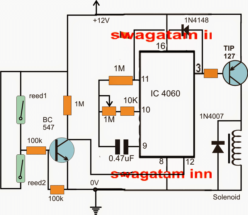
The Design#1
Referring to the diagram above the proposed solenoid timer with reed switching can be seen configured across a single timer/counter chip 4060.
As long as the reed switches are not triggered, the pin12 of the IC stays high through the 1M resistor, however if either one of the reed switches is triggered, the BJT is forced to conduct and ground pin12 of the IC which in turn gets reset and triggers the solenoid via the TIP127 transistor, the IC now begins counting. After 30 seconds (which may be varied or customized as per individual preference via the 1M pot), pin3 of the IC goes high causing the TIP127 to deactivate itself and the solenoid.
The positive feedback through diode 1N4148 to pin11 makes sure that the IC gets latched in this position until the reed switch is released and the IC gets reset to its original state.
Circuit Request#2
I am Student of Dwi Raya University from Indonesia,
i have request for you to make Timer with 2 Selector Timing Schematics.
If this Timer is :
- select Button 1 ON, Timer work 3 Hours ON and 3 Hours OFF will be continuously Repeat as long as power supply is available
- select button 2 ON, Timer work 6 Hours ON and 6 Hours OFF will will be continuously Repeat as long as power supply is available
Please Help me Sir,
Thanks and Best Regards,
Stevanie
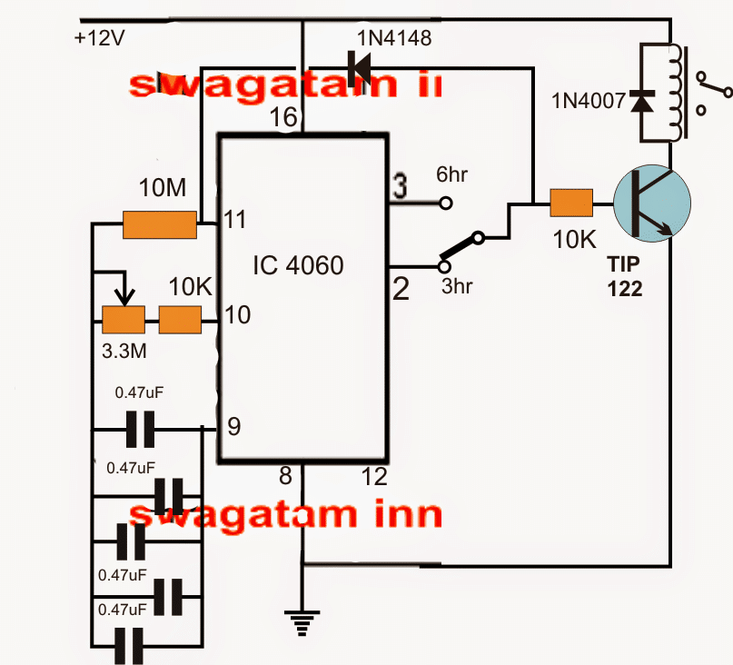
The Design#2
As per the request, the 3/6 hour selectable timer circuit may be studied above. Again a 4060 comes to the rescue and implements the application by including minimum number of parts.
The IC is configured in its standard timer configuration.
The 3.3M pot along with the 0.47uF capacitors determine the preferred adjustable time interval across the shown pinout 3 and 2.
The pin3 is set to provide the required delay of 6 hours, so that pin2 allows to acquire a 50% less that is a 3 hour delay option.
The above is appropriately selected through a SPDT switch wired as shown in the diagram.
The feedback diode ensures a latching action which may be simply removed if a continuous ON/OFf sequence is desired by the user, indefinitely.



Questions & Answers
La circuitul Nr 2 de mai sus,cum pot sa fac sa lucreze 10 secunde și să se oprească 10 minute.Va rog ajutor.Multumesc.
You can try the following concept. Make the pot value to 2.2 meg, and the capacitor value to 220uF or higher:
Please give me circuit diagram of adjustable timer up to 60 minuts with 7 segment display.
You can try this:
https://www.homemade-circuits.com/simple-digital-timer-circuit-with-2-digit-display/
Hi Mr Swagatam,
I must compliment you on the excellent work in helping the masses to build practical circuits.
I have been searching your site for timer for my watch winder. So far, I don’t seem to be able to find one.
My requirements : To switch on a relay (for the motor) for 15 mins (ON), then off for 2hrs (OFF). And the cycle repeats as long as the power is available. Ideally, the ON duration can be adjusted from 10 – 30 mins and the OFF duration can be adjusted from 1 – 3 hrs.
Appreciate your suggestion.
Thanks.
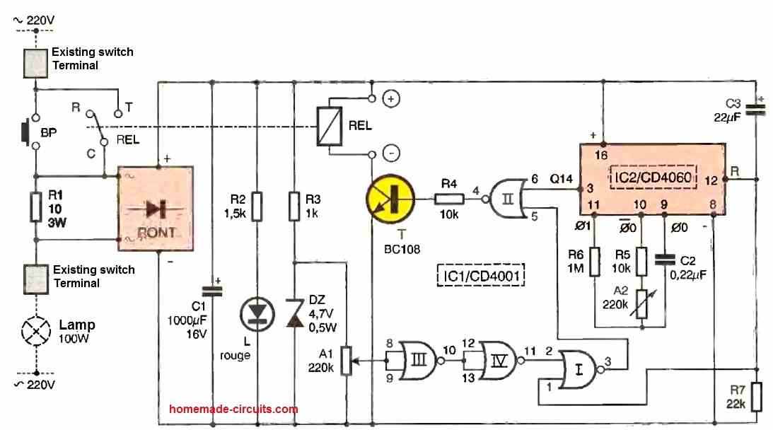
Thank you YK, I think you should try the following configuration, this one should fulfill your requirement perfectly:
Simple Programmable Timer Circuit
I am doing demo project for motor run forward and reverse with control of limit switches (window lifter up and down respectively)
the reed switch placed in two fixed places for attracting the by magnet .the magnet placed at motor gear teeth. upper and lower reed switch attracted by the magnet accordingly motor will run at forward and reverse the condition.
Operating conditions :
1, motor move forward at a certain distance until the upper side reed switch attracted by the magnet. when the power supply switch on.
2, when reed switch attracted by the magnet remains the stop at 1-minute delay-off and start to reverse direction.
3, the motor move reverse at a certain distance until the lower side reed switch attracted by the magnet.
4.when reed switch attracted by the magnet remains the stop at 1 minute and start to forward direction.
I want this cycles continuously running. I hope better reply here from you
I will try to figure it out if possible.
Hello Sir,
I want to know that is there any change in the set frequency if we change the applied input voltage.
If yes what is the relation between input voltage and frequency.
Hello Tushar,
Normally it won’t have much effect, still it’s better to use a voltage regulator only for the IC to ensure an assured performance.
Performance of CMOS based ICs are mostly not affected by voltages between from 5V to 15V…
please I have a project that is use for car security in Nigeria. the little I know about it is that it has a caps, diodes, resistors and transistor. it uses a 12V supply and takes 6mins to cut a repay when the driver's door is open. the relay is close by pressing a push button switch. it also have another normal switch that can be close if I need not use the door control to switch off the relay. please can you help me to design the circuit.
elvis4best@gmail.com
Elvis, it's a just delay ON relay timer, you can try the following concept
https://www.homemade-circuits.com/2013/02/make-this-simple-delay-on-circuit.html
Sorry, but I don't know what the "standard formula" is for adjusting the delay time.
Ideally the delay should be adjustable from 3 to 60 minutes, but I'm willing to settle for 20 minutes fixed.
use R = 22K for the resistor, and C = 1uF for the capacitor….record the time delay from pin#3.
using this yardstick (values) you can calculate any other desired delay through simple cross multiplication of the R/C values
I would like to purchase a "delay on make" 24V timer with a variable delay of 3-60 minutes, but I can't find one available. I am resorting to making my own. Please help with a source or circuit diagram if possible. Thank you!
you can try the second circuit from the above article and use it for your purpose
you can do it by appropriately calculating the capacitor and the resistor values..this could be done by trial and error or by the standard formula
Very good info. I need to turn on a bin vibrator for a 30 second duration when power is applied then turn off even if the power stays applied and then only run again when power is turned off and back on again. Oh and it is a 20a 115v ac circuit
thanks!!, for your application you can try the following circuit:
https://www.homemade-circuits.com/2012/01/how-to-make-simple-timer-circuit-using.html
just remove the push button and short the points together.
across pin3 and ground you can connect a relay for controlling the vibrator.
make sure the relay has a freewheeling diode.
Dear Mr. swag,
I am happy to see all the the projects here in this site and found out all useful for interested electronic hobbies. For that I was challenge to assemble an automatic aircon main control switch. Please help design additional circuit in the following sequence:
Using the circuit requested by Mr. Stevanie (6hrs Auto on and off) what should be the best circuit to incorporate in order to properly and automatically activate the main control of my aircon from OFF state to LOW FAN, HIGH FAN, LOW COOL and HIGH COOL. Cause I believed that turning on an aircon automatically would have to follow the appropriate sequence and time interval before reaching it to high setting.
Please extend a big help and notify me with my email: rieno.cuizon@gmail.com.
Best regards,
Rieno.
Thank you dear Rieno,
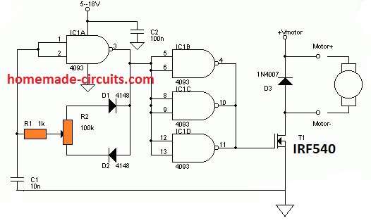
you will need a PWM circuit for controlling the speed of the AC motor, would you be able to make a PWM circuit in addition to the timer circuit? It could be a lot complex for a new hobbyist