• Skip to main content
  • Skip to primary sidebar

Homemade Circuit Projects

Need circuit help? Post them in the comments! I've answered over 50,000!

Blog | Categories | About | Contact | Calculators-online
You are here: Home / Voltage Control and Protection / Automatic Voltage Regulator (AVR) Circuit

Automatic Voltage Regulator (AVR) Circuit

Last Updated on January 2, 2024 by Swagatam 8 Comments

An automatic voltage regulator circuit is quite well used where Voltage supply is only 120VAC. Many gadgets can operate good at 220V Ac that is why Voltage regulation is needed.

Table of Contents
  • Circuit Operation:
  • Auto cut Circuit:

By: Mehran Manzoor

For this matter an appropriate voltage Regulator circuit is designed which can operate up to capacity of 1KW and gives Variable voltage at different steps (ranges).

Regulator circuit is designed which can operate up to capacity of 1KW and gives Variable voltage at different steps (ranges)

Circuit Operation:

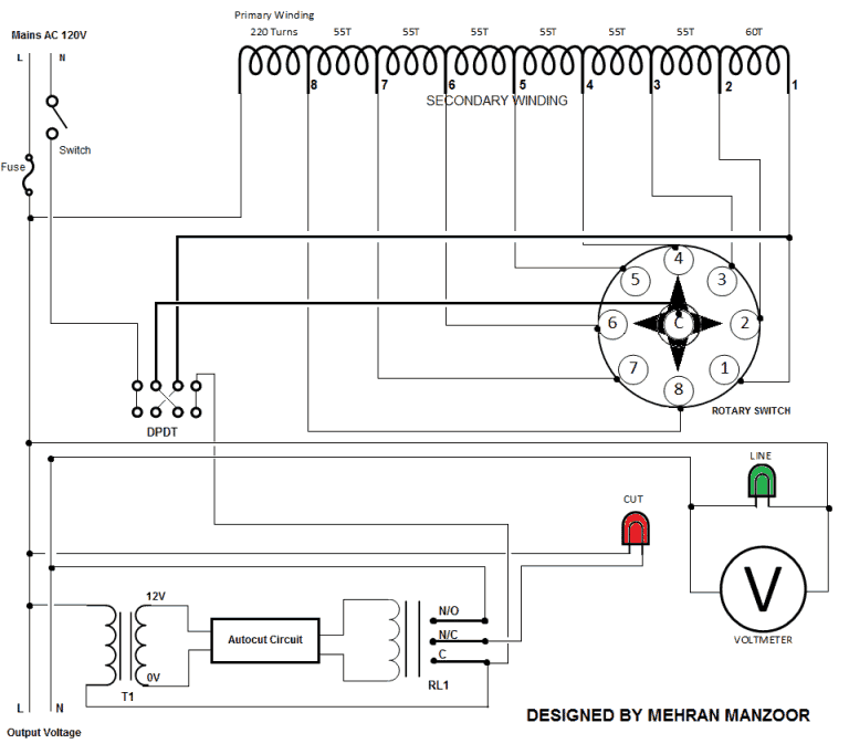
The Mains 120V AC Line and Neutral contains a switch and a fuse up to 10A. The DPDT Switch is used for Voltage up and Down. DPDT Switch has a four ends.

The Neutral from mains enters directly in first end of DPDT and the Line/Phase enters the transformer primary winding which is of 220 Turns of 6 layers.

It has seven Secondary Winding of 55 turns and one winding of 60 turns. These windings are connected to Rotary switch 1 to 8 respectively. The rotary switch has eight steps which can selected on by one.

The common of rotary switch are connected to second end of DPDT switch. The third end of DPDT are connected to first secondary winding of transformer.

The last end of DPDT are connected to Common of relay. The relay in a circuit is used for Auto cut off.

The N/O of Relay becomes the first output Mains AC Supply.

The N/C of relay is connected to first terminal of Red Neon lamp as an indicator to detect the auto cut off. the other terminal of Red Neon lamp is connected to other terminal of output Supply which is common to circuit. It directly comes from Line/Phase wire of Input mains 120V AC.

The common of relay is connected to fourth end of DPDT switch and second terminal of 500mA transformer for sensing the voltage. the relay can operate from Auto cut Circuit as shown in Diagram.

The Voltmeter is connected parallel with Green Neon Lamp to output Supply which indicates the presence of power and voltage across the output terminals
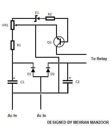
Control2Bcircuit

Auto cut Circuit:

The above automatic voltage regulator circuit clearly shows that AC 12V enters through 500mA Transformer to auto cut circuit.

The two Capacitors C1 and C2 adjoining with D1 and D2 produces first terminal to relay and other terminal can be adjusted by preset which are joined to emitter of Transistor Q1.

The output produced by collector becomes another terminal to relay. the value of the preset can be adjusted as per required. When the voltage is reached above the adjusted value the circuit automatically cuts off.

Parts Required for Auto cut circuit:

C1-C2: 100μ 25V
D1-D2: 1N4007
R1:1.5KΩ
R2:220Ω
VR1: 5K preset
Z1: 8.2V
Q1: BC547

You'll also like:

  • 1.  How RCCB Works [with Circuit Diagram]
  • 2.  Simple Voltage-to-Current and Current-to-Voltage Techniques – By James H. Reinholm
  • 3.  DC Power Controller Circuit
  • 4.  Mains AC Overload protection Circuit for Voltage Stabilizers
  • 5.  AMS1117 1A LDO Voltage Regulator IC – 3.3V, 1.8V, 2.5V, 5V Regulators
  • 6.  SCR/Triac Controlled Automatic Voltage Stabilizer Circuit

Filed Under: Voltage Control and Protection Tagged With: Automatic, AVR, Regulator, Voltage

About Swagatam

I am an electronics engineer and doing practical hands-on work from more than 15 years now. Building real circuits, testing them and also making PCB layouts by myself. I really love doing all these things like inventing something new, designing electronics and also helping other people like hobby guys who want to make their own cool circuits at home.

And that is the main reason why I started this website homemade-circuits.com, to share different types of circuit ideas..

If you are having any kind of doubt or question related to circuits then just write down your question in the comment box below, I am like always checking, so I guarantee I will reply you for sure!

Previous Post: « 2 Simple Light to Frequency Converter Circuits for Transforming Light into Pulses
Next Post: How to Select the Right Charger for Li-Ion Battery »

Reader Interactions

Comments

  1. din muhammad says

    September 2, 2022 at 3:12 pm

    sir we need a simple and easy circuit like this for Automatic voltage regulator please conform some expert and send thanks

    Reply
    • Swagatam says

      September 2, 2022 at 6:18 pm

      Hello Din,

      you can try this very simple concept of an automatic voltage stabilizer circuit:

      https://www.homemade-circuits.com/how-to-make-small-homemade-automatic/

      Reply
  2. din muhammad says

    January 27, 2022 at 10:45 am

    sir, give the bibin size and wire gauge for primary and secondary. thanks

    Reply
    • Swagatam says

      January 27, 2022 at 1:43 pm

      Din, I don’t know about the exact transformer specifications. I can only provide the voltage rating.

      Reply
  3. din muhammad says

    October 22, 2021 at 3:36 pm

    Sir, Please inform me about the wire gauge for primary and secondary turns. Thanks

    Reply
    • Swagatam says

      October 22, 2021 at 4:24 pm

      Sorry, I do not have the details, because the idea was submitted by another author.

      Reply
  4. Ram Ryan says

    March 3, 2016 at 12:26 pm

    Good info, but its Auto Cut Voltage Regulator not Automatic Voltage Regulator

    Reply
    • Swagatam says

      March 3, 2016 at 3:35 pm

      You are right Ram, actually I did not read the article before publishing.

      It's actually a manually adjustable auto-transformer with unsafe voltage cut off.

      Reply

Need Help? Please Leave a Comment! We value your input—Kindly keep it relevant to the above topic! Cancel reply

Your email address will not be published. Required fields are marked *

Primary Sidebar


Subscribe to New Posts

Categories

  • Arduino Projects (88)
  • Audio and Amplifier Projects (132)
  • Automation Projects (17)
  • Automobile Electronics (101)
  • Battery Charger Circuits (83)
  • Datasheets and Components (104)
  • Electronics Theory (143)
  • Free Energy (37)
  • Games and Sports Projects (11)
  • Grid and 3-Phase (19)
  • Health related Projects (25)
  • Home Electrical Circuits (12)
  • Indicator Circuits (14)
  • Inverter Circuits (88)
  • Lamps and Lights (142)
  • Meters and Testers (69)
  • Mini Projects (46)
  • Motor Controller (64)
  • Oscillator Circuits (27)
  • Pets and Pests (15)
  • Power Supply Circuits (108)
  • Remote Control Circuits (50)
  • Security and Alarm (64)
  • Sensors and Detectors (101)
  • Solar Controller Circuits (59)
  • Temperature Controllers (42)
  • Timer and Delay Relay (49)
  • Transmitter Circuits (29)
  • Voltage Control and Protection (38)
  • Water Controller (36)

Tags

Alarm Amplifier Application Arduino Automatic Battery Charger Circuits Control Controlled Controller Current Datasheet DC Detector Digital Driver Electronic Explained Explored Generator High Indicator Inverter Lamp LED Light Meter Motor Pinout Power Regulator Remote Sensor Simple Single Solar Supply Switch Timer Transistor Voltage Water Watt Working


Other Links

  • Privacy Policy
  • Cookie Policy
  • Disclaimer
  • Copyright
  • Videos
  • Sitemap


People also Search

555 Circuits | 741 Circuits | LM324 Circuits | LM338 Circuits | 4017 Circuits | Ultrasonic Projects | SMPS Projects | Christmas Projects | MOSFETs | Radio Circuits | Laser Circuits | PIR Projects |

Social Profiles

  • Twitter
  • YouTube
  • Instagram
  • Pinterest
  • My Facebook-Page
  • Quora
  • Stack Exchange
  • Linkedin


  • Recent Comments

    • Swagatam on 10 Useful Active Filter Circuit Diagrams Explored
    • Swagatam on Treadmill Motor Speed Controller Circuit
    • Swagatam on IC 741 Power Supply Circuits
    • Swagatam on Simple Capacitive Discharge Ignition (CDI) Circuit
    • Paul Hess on 10 Useful Active Filter Circuit Diagrams Explored

    © 2025 · Swagatam Innovations