Hello friends, today we will discuss about a very interesting high voltage solar panel battery charger circuit. Many people ask how to safely charge battery from high voltage PV panels like 100V to 450V. So today I am explaining the complete step by step working of this circuit.
Power On and Initial SCR Latching
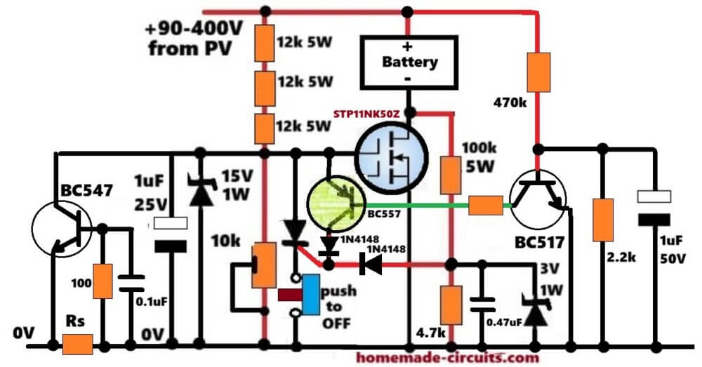
Assuming your voltage is normal, when you turn ON the solar panel high voltage supply, the main MOSFET STP11NK50Z cannot switch ON immediately. Why this happens? Because 1uF 25V capacitor connected across its gate creates delay and prevents instant turn ON. Because of this initial delay, the MOSFET stays OFF and full high voltage coming from PV panel passes through the battery (+) and appears at battery (-) terminal, which is connected to MOSFET drain.
Now from drain line, this voltage enters the 100k 5W and 4.7k resistor divider network. Voltage gets reduced and passes through 3V 1W Zener diode and 1N4148 diode. This instantly gives trigger pulse to SCR gate. The moment SCR gets gate pulse, it turns ON and latches the MOSFET gate directly to ground through the push to off switch. So at this initial stage MOSFET strictly remains switched OFF for safety.
Manual Starting of Battery Charging
Now to start the battery charging, you have to manually press the push to off switch once. The moment you press this switch, the current path to ground breaks, so SCR latching breaks and SCR turns OFF.
As soon as SCR turns OFF, gate voltage builds up across the 15V 1W Zener diode from 12k 5W resistor chain. MOSFET turns ON fully. Once MOSFET switches ON, its drain voltage drops down near to 0V. Because drain becomes 0V, the triggering voltage at SCR gate completely disappears. So even after you release the push to off switch, SCR stays permanently OFF and MOSFET stays ON. Now in this normal condition, battery charging starts smoothly through MOSFET.
Full Charge Auto Cut Off Working
Now let us see what happens when battery becomes fully charged. As battery voltage rises towards full charge level, potential at base of BC517 Darlington transistor increases. When full charge limit reaches, BC517 turns ON.
When BC517 turns ON, it pulls down base of BC557 PNP transistor and turns BC557 ON. BC557 then sends positive supply from its collector through 1N4148 diode directly into SCR gate. SCR once again receives gate pulse, turns ON instantly and latches MOSFET gate back to ground. MOSFET turns OFF and battery stops charging immediately. This takes care of automatic overcharge protection.
Low Voltage Deep Discharge Protection
Now suppose solar panel voltage drops down or battery voltage becomes too low. What happens in low voltage situation? The voltage coming through triple 12k 5W resistor chain and 10k preset drops down below threshold level required for MOSFET gate drive. So MOSFET turns OFF.
The second MOSFET turns OFF, its drain voltage immediately jumps high because panel potential comes through battery (-) path. This high voltage again travels through 100k and 4.7k divider and 3V Zener diode to feed SCR gate. SCR again turns ON and latches. MOSFET gets locked out permanently until manual reset. This completely protects battery from deep discharge and low voltage issues.



Need Help? Please Leave a Comment! We value your input—Kindly keep it relevant to the above topic!