A practical electronics engineering resource focused on tested circuit projects, clear theory explanations, design calculations and real world troubleshooting support for students, hobbyists, and professionals.
Questions Answered with Practical Working Solutions
Backed by more than two decades of hands on circuit design experience, reader questions posted in the comments are reviewed and answered personally. Wherever necessary, circuit corrections, design improvements, and verified working solutions are provided to ensure accuracy and reliability.
How To Use This Website
- Start with the Electronics Tutorials section if you are new to circuit design.
- Explore application based projects to find ready to use circuits.
- Read the comments for practical tips, corrections, and reader discussions.
- Post your questions to get guidance and improvements where needed.
Learn Electronics Step By Step
Electronics Tutorials

Foundational tutorials explaining electronic concepts, calculations, and working principles in a simple and practical way.
Semiconductor Theory
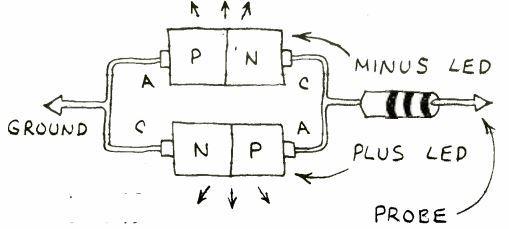
Detailed explanations of semiconductor devices and circuit theory with practical examples and applications.
Arduino and Microcontrollers

Arduino programming tutorials and microcontroller based automation projects with complete circuit details.
IC 555 Timer Circuits
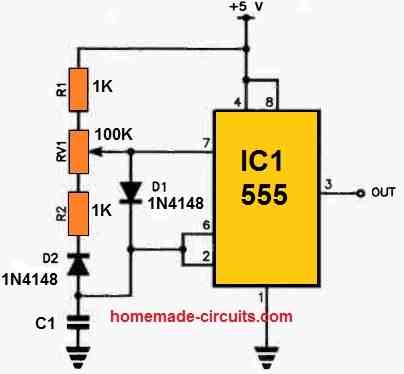
Classic and modern IC 555 timer circuits explained with calculations, diagrams, and application ideas.
Power Electronics and Energy Systems
Inverter Circuits
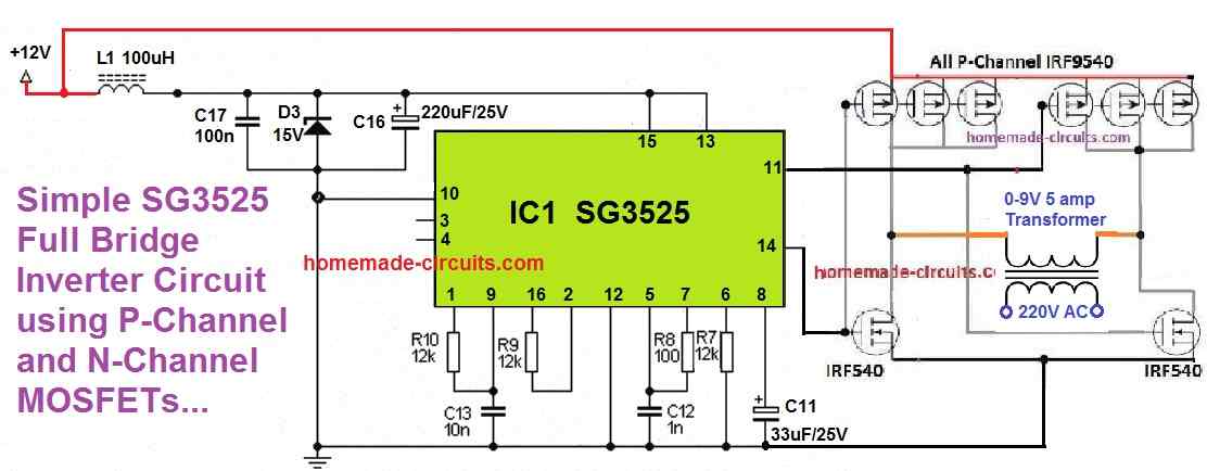
Designs that convert DC power into 220V AC with explanations ranging from basic to advanced sine wave systems.
Battery Charger Circuits
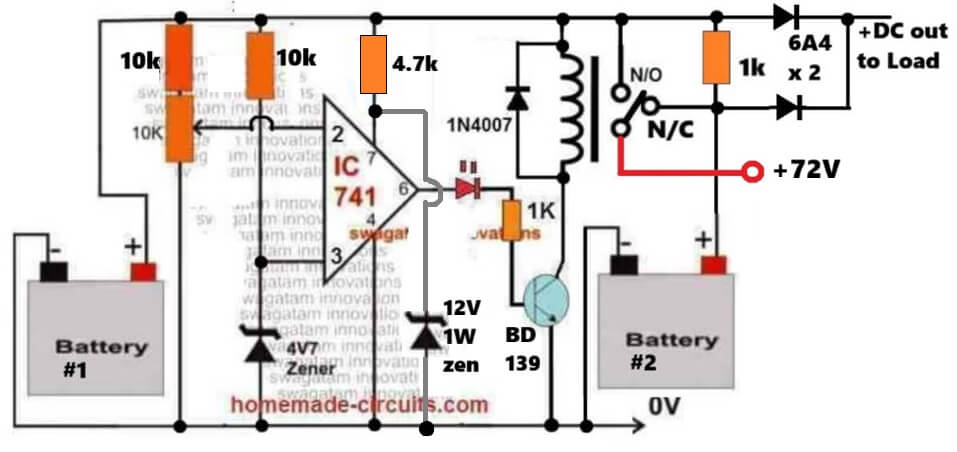
Controlled battery charging circuits covering lead acid, lithium, and industrial battery systems.
Power Supply Circuits
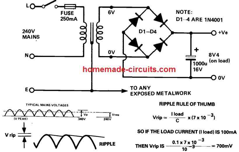
Fixed and variable voltage power supply projects for workbench testing and embedded applications.
Solar Controllers
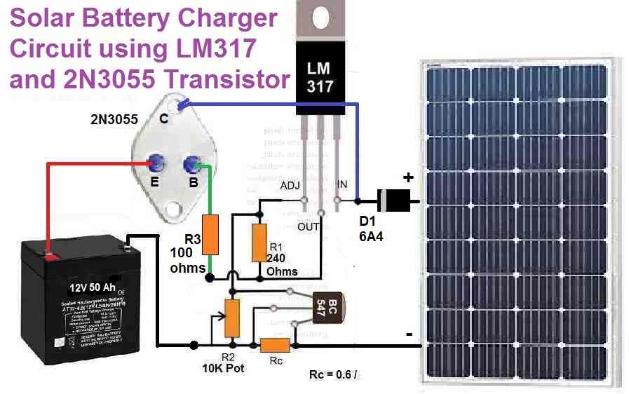
Solar charge controllers and renewable energy projects using PWM, MPPT, and microcontroller techniques.
Application Based Electronic Projects
Home Electrical Projects
Electronic circuits designed to enhance safety, automation, and efficiency in home electrical systems.
Industrial Electronics
Control and automation circuits used in industrial machinery and process systems.
Automobile Electronics
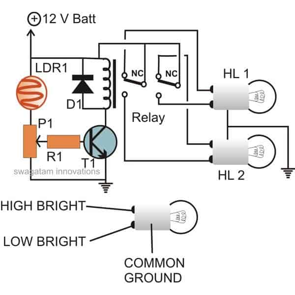
Automotive electronic projects for lighting, safety, and performance enhancements.
Motor Control Projects
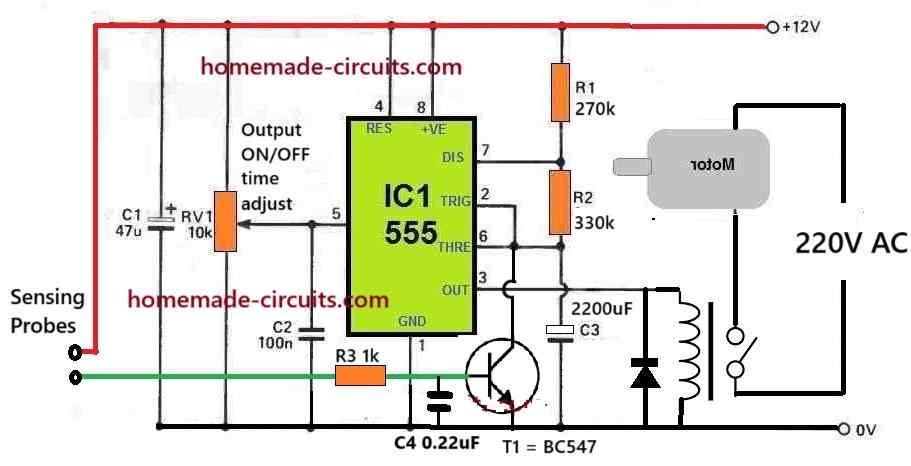
Speed and torque control circuits for DC and AC motors used in home and industrial applications.
LED and Lighting Projects
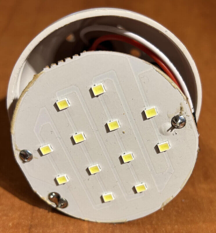
Decorative and functional LED lighting circuits including dimmers, chasers, and drivers.
Remote Control Circuits

Wireless and IR remote control circuits for convenient device operation from a distance.
Specialized and Utility Circuits
Wireless and GSM Projects
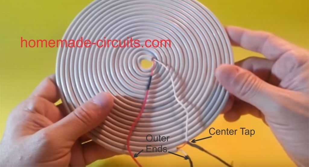
Wireless control and GSM based communication projects for monitoring and automation.
Meters and Testers

Hand-built electronic meters and testers useful for diagnostics and troubleshooting.
Timer and Relay Circuits
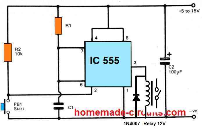
Delay timers and relay switching circuits for automation and protection applications.
Learning Through Discussion
A lot of the circuits here slowly get better through questions and discussions in the comments. Readers point out real world problems, ask for small changes, or request clarifications, and over time this back and forth helps turn the designs into more reliable and practical working circuits.
Try and Test Circuits Online
To help readers better understand how circuits behave, this website also includes a simple online circuit simulator. It can be used to visualize basic circuit operation, test component changes and explore circuit behavior before building it practically.

Recent Community Discussions
Latest questions, answers, and circuit improvements discussed by readers and the author.
No, you can use any number of capacitors as long as the total capacitance and ripple current rating are enough…
which schematic are you referring to?
can i use the same schematic for the two half bridge IC but for the MOSFET i will use IRF840…
Goodday sir, I want to ask that is it compulsory to put 6capacitor in parallel to make a input filter…
Hi Solomon, you can try the concepts explained in this article: https://www.homemade-circuits.com/inverter-circuit-with-feedback-control/


Common Problems Addressed
- Circuits that do not work as expected after assembly.
- Confusion about component values and calculations.
- Improper power supply or overload issues.
- Noise, heating, and instability in practical circuits.
- Modification of existing circuits for custom requirements.
Note: All circuits are provided for educational and experimental purposes. Readers are advised to follow proper safety precautions while working with mains voltage and high power circuits.
Questions & Answers
please let me join and get your projects
I would like to know the values of R 45 and R 49 in Microtek VO 3.32 UPS board. In one circuit diagram it is 100K ohm both. Installed resistors in my board are 47 ohm each.Thank you.
Sorry, I do not have sufficient information regarding your question at this moment.
Thank you very much!
Good morning, I’m Carlos Velazquez. I hope you are in good health.
I’m trying to make a circuit that illuminates a painting at night for 14 hours. Starting at 6:00 p.m. and turning off at 8:00 hrs. The lighting is with LED, it must be activated with LDR when capturing the darkness outside and sending a signal with RF 433mhz and turned off when capturing the light by sending a signal to the receiver.
The transmitter must be outside the house powered by a solar cell that recharges a battery that does not consume much current and inside the receiver with a rechargeable battery, this process is daily.
For your attention, I thank you for your time and support.
Good Morning Carlos,
I will design the circuit and post it as a new article. Once it is done I will let you know.
Hi, how is LED lamp powered? Is it through a chargeable battery or from an AC outlet indoors. If AC outlet is available indoors then the receiver battery can be also charged through this AC source.
Yes, it is a rechargeable battery that is inside the house, could you suggest which battery to use? Thank you for your time
The battery voltage and Ah specifications will depend on the LED specifications. If you tell me the LED specifications, I can figure out the battery specifications.
How would you charge this battery, is it through the home AC outlet or through a solar panel?
Disculpe, no encuentro mi comentario donde lo podre encontrar y verificar el favor que le pedí.
The comment might have disappeared for you maybe due to the automatic clearing of the site cache, but no worries, I have received your comment and will try to design it soon.
I’m Chibueze Nwakpuda from Nigeria, a regular follower of your blog. Please sir, I am experiencing difficulty in building electric stove using plaster of Paris (poo) as my element base. The pop cracks when heated. Kindly advise me on the substance I can place my heating spring coil element on that cannot crack.
Thank you.
Hi Chibueze, Sorry, I have no idea how the Pop cracking problem can be solved, it is beyond the scope of my expertise.
Good afternoon, regarding the LEDs, I did a test with 6 LEDs but I need more light, so I ask your suggestion which would be the ideal one and regarding the battery, as you told me, it can be either solar or AC rechargeable.
I thank you for your attention and support of this important project for me. Thank you.
It will be difficult for me to know how much light you need for the painting. It will depend on the size of the painting, and the number of paintings.
If 6 LEDs are not enough, you can try 10 LEDs.
I will also need to know the specifications of the LEDs you are using (Voltage and current rating)
The LEDs are 3.4 v, 20 mA white, it is only 1 square of 44 x 60 cm. Thank you.
OK, I have designed the circuit, you can find the post in the following link:
https://www.homemade-circuits.com/automatic-night-activated-wireless-light-circuit-for-paintings/
I have simple mosfet wire loop security device but there is an issue the thieves can can joint the loop before the protected gadget thus making the system normal and steal the protected gadget can you design a wire loop circuit such that it activates alarm on both cutting and jointing the loop
Please i will be very thankful
Hi Swasti,
If the intruder already knows the location of the trip wire and manually fixes it then there’s nothing we can do. The trip wire or the loop wire is supposed to be hidden from the intruder, if it is visible or known to the intruder then it is impossible for it to work effectively. In that case better to install a simple PIR based alarm circuit or a motion detector alarm circuit.
Thank you sir
Yes sir i have considered pir based alarm and think but In my case there in the protected area sometimes animals like dogs and cats are walking so it is possible that most of the times my PIR based alarm will give false alarms therefore it is failed
Kindly if you have another idea or circuit then please guide me i need your support please
Hi Swasti,
Yes, PIR sensor or any other motion sensor will detect animals also and give false alarm, which cannot be avoided.
I think a vibration sensor can be the best option in that case, which will detect strong vibrations if an attempt is made to remove the solar panels from their installations.
Let me know your thoughts on this.
Sir you are the expert if you consider it helpful then i will be waiting for the circuit diagram of vibration sensor please make i perfect diagram so that i make the device soon
I appreciate ?
Thank you Swasti,
According to me the first circuit from the following article will be most suitable for you:
https://www.homemade-circuits.com/simplest-sound-activated-relay-switch/
You can reduce the sensitivity of the MIC simply by increasing the value of R1 to 10k or 22k or 33k.
You can enclose the whole circuit in a plastic box and clamp it with your solar panels. If anybody tries to remove the solar panels or tries to tamper with the circuit box, the relay will be instantly activated causing the alarm to sound.
If you want more information about the circuit details or the construction you can comment under the above linked article post, I will try to sort it out for you.
I find this site very educational, thank you Swagatam and everyone.
I have the a need for the following device. Would be grateful for your help in building it.
—————————-
Light trap for Insects : the device turns on LED light automatically at dusk for 2-4 hours and attracts harmful insects in a crop field.
Device should not overcharge the battery, nor allow it to be depleted below a certain level to extend battery life.
Device should have a switch to manually turn the lights on and off.
The device should use low cost components since I need to deploy many of these devices.
The device should be essentially weather proof as it will be deployed in open field.
Thank you in advance for your help!
Thank you OP,
I will try to design the circuit soon, and let you know once it is done.
Thank you Swagatam, truly appreciate your help in this regard.
Thank you OP, I have published the article, you can find it under the following link:
https://www.homemade-circuits.com/insect-light-trap-circuit-for-protecting-crops/
Pls can I see some of this components to buy in Nigeria
Hi boss, thanks for the circuit diagram. But I have some issues. 1, I don’t understand what kind of dieyot is D3 and I can find 48volt relay, is there any resistor I can use to convert it to either 12or 24volt relay. 2, which of the virable resistors is responsible for setting the low voltage level. Like if I want the relay to come or at either 50,40 or 30 percent. Thanks for all your response.
Hi Jolly, which circuit are you referring to? Please reply under the same comment so that I can refer to the circuit diagram.
The 48volts monitoring relay circuit
Sorry I cant find the original post where you posted you previous question.
Hi, I can’t find it either. But I received a circuit diagram for the 48volts battery monitoring relay. The idea was that the system is a 48volts system. The device was to monitor the 48volts when the voltage get low to like 30 or 40 percent a relay on the monitoring device should switch on and when the battery goes to full level the relay should switch off. I got a circuit diagram from you today about it but there are some things I’ll want to to look into on the drawing.
Your initial question was posted under the following article. Please ask it under the same thread, I will try to help:
https://www.homemade-circuits.com/3-step-dc-voltage-level-monitor/
I have a relatively high impedance voltage source that puts out +/- 200 mV depending on the pH of the solution it is exposed to. I would like to have a simple op-amp based circuit that would apply a opposing voltage to this device such that net zero current flows. I would be monitoring the opposing voltage. The overall impedance is of the order of 1 MOhm, so the short circuit current otherwise will be in nanoamps. So the need is for a zero current, constant current circuit…
Your thoughts are most appreciated…
As per my understanding, you want another 200mV DC source through an opamp that could be connected with your existing 200mV?
Please let me know if I understood it correctly.
Yes basically so. It will end up applying exactly negative of the voltage the exiting probe is generating, in the extreme +/- 450 mV.
Sorry, I am still having problems understanding the configuration.
Do you want to sink the existing 200mV source to GROUND?
This can be done by shunting the source to ground with a jumper, what is the role of the op amp supposed to be here?
HI
is there a component tester for intergrated ccts eg LM386 ?
Hi, the easiest way to test the IC is by building its basic configuration as shown below:
https://www.homemade-circuits.com/wp-content/uploads/2012/08/lm386amplifierwithgain20.png
The pot is not required. Simply touching the pin#3 directly should cause the speaker to generate a loud buzzing sound, indicating a good IC.
Hi, I’m Albrecht.
I’m looking around for a low noise amplifier for very tiny amounts of charge. For low low noise reasons I consider to use an Agilent ATF-55143, Although this device is made for rather high frequency applications in my case the required frequency band is more like “DC”, i.e. 10kHz up to 3MHz. Are there somewhere advices how to bias in an optimal way the pHEMT in order to get the maximum S/B ratio?
Hello Albrecht,
Did you check its datasheet, I can see some related information being available at the bottom section of the datasheet.
https://www.farnell.com/datasheets/33952.pdf
lm386 is running very hot very hot to touch is this normal?
It is not normal, how much supply voltage did you use? Try with 5V first then try 9V.
Hi sir..I want to build a personal website filled with my personal electronics design interests and wish to build my skills with a dedicated storage space organized neatly.So please help me on how to create website like yours.
Hi Girish,
You can create and manage a website cheaply on a WordPress platform.
Learning WordPress is a comprehensive process and can take many months to master. However as far the initial setup is concerned, you don’t have to worry at all, since it will be done by your hosting provider. You can also take their help to further learn regarding how to optimize your WordPress site. Go for hosting provider who offer the best SSD storage with litespeed cache, compare the plans and select which you find the most economical.
Hi All,
I am needing a small circuit that runs a motor for exactly 3 rotations.
Wondering the best way to achieve this? The start needs to be triggered by a random input from a light that will go on and then off and the rotations are independent of the light being on – so there is a separate power source for the motor which supplies the motor.
I am thinking if possible, the light triggers the closure of the motor circuit starting the motor. An optical interrupter then closes three separate transistor switched circuits. When the 3rd circuit is closed, this then opens the motor circuit. This should also ignore any subsequent trigger events while operating so I am guessing the circuit from the trigger source (light) needs to be open between the motor being triggered and stopping.
Hope this makes some sense. Getting back in to all this so pardon any odd explanations. Thanks
Michael
Hi, thanks for the question.
I guess the light needs to remain ON until the 3 rotations are completed by the motor, otherwise, in the absence of light the opto-interrupter might not be able to sustain the triggers for the 3 transistor switches?
Please Let me know if I am correct.
Thanks for the prompt response. I should clarify that the light is external to this design. It is a merely an intermittent light that I need to use as a trigger only. It is intended that the motor will have a disc with a “tag” which passes through the opto-interrupter with each rotation. So each time the opto is opened/closed it needs to do something so that on the third rotation it shuts off the motor. Hopefully that helps.
Seems like my last reply didn’t make it to the thread.
Thanks for the prompt reply. The light is essentially the trigger to start the motor. Its circuit provides the input to the motor circuit. So when the light flashes the motor needs to turn 3 times even though the light circuit is off. So the motor has its own power and its circuit is closed when the light flashes and opens after three rotations. The motor has a disc with a small plate that passes through the opto. I am thinking that this could be used to eventually open the motor power circuit on the 3rd rotation. Hopefully this makes it a little clearer.
Thanks for the clarification.
Your last reply was also received and posted.
Ok, the external light is only for the initial triggering for the motor.
That means the opto-interrupter should be having its own light, such as an LED for implementing the switching actions, right?
If yes, then i think the whole operation (until switch off after 3rd rotation) can be implemented using a 4017 IC.
Thanks so much for the lead. I have read up on the 4017IC and agree that it looks promising. Another question is that the specs talk about CLOCK pulses and it identifies the use of the 555 IC. Is this because of the shape of the pulse? Or could the opto to just pass the positive charge to PIN14? Or do you think I should use the opto to trigger the 555 IC to send a CLOCK pulse?
I think the opto can be directly configured with pin#14 of the IC 4017 and will work well, no need of employing a 555 monostable in the middle.
This leads to another question … the opto is essentially always on (correct?) so when the “cam” passes through the opto it will close the circuit on the collector side of the opto. Closing that circuit then provides the pulse for PIN#14 on 4017IC. Have I got this right?
You are absolutely right. You can also reverse the action by connecting the emitter side of the opto transistor with pin14. A resistor of around 100k will need to be connected between pin14 and ground.
I have run into a small problem … The external light flashes and that raises the voltage at the base of the NPN transistor which closes the circuit to start the motor. Correct so far? The problem (afaik) is that circuit will open when the base voltage drops and the motor will stop. I have worked out the 4017IC usage to count 3 turns and then stop. The motor is geared down to roughly 1 rev per sec. How do I keep the motor circuit closed after the initiating flash?
I think the following circuit should be able to solve the problem:
https://www.homemade-circuits.com/wp-content/uploads/2024/04/simple-delay-hold-timer-circuit.jpg
Make sure to replace the BC557 with TIP127 (or as per the current rating of your motor) and you can alter the values of the 470uF and the 22k resistor to adjust the delay OFF time as required.
Thanks for your help with this. So I now have an opto-controlled circuit working well on a 5V circuit divided from a 9V battery. I need to turn the motor on and off from the collector of the opto. It works fine for an LED but not for the motor which needs >7V (the LED is getting approximately 1.5V). I am guessing here that I use a diode to the base of an NPN transistor to open and close the higher voltage circuit that the motor is on? If so, how do I get this to work as the transistor does not seem to be switching … its always on at the moment. If there is another way to do this, what would your suggestion be? Thanks
Can you please tell me which opto-coupler you have used? And also please provide the voltage and current specifications of the motor. I will try to solve it for you.
The opto is ZD1901 (Vf = 1 to 1.3) I am seeing 1.95V at the collector. The motor specs are here 55RPM 12VDC Reversible Gearhead Motor | Jaycar Electronics. Thanks. Appreciate your help.
Thanks for the information.
The opto transistor will not be able to handle the motor directly, since the motor is too heavy for the opto transistor.
Could you please explain how do you wish to configure the motor with the opto-interruptor?
Please explain the working of the configuration in short.
The opto-interrupter circuit needs to work on a 5V circuit so I am just using it to switch on and off. The motor needs to run off a 6 to 12V circuit so I am thinking it will be on a separate circuit which is switched on and off by a transistor with diodes connected to the collector??
You can try one of the methods explained in the following article:
https://www.homemade-circuits.com/how-to-drive-relay-through-opto-coupler/
The relay coil can be replaced by your motor. The 1N4007 will remain as is, parallel to the motor connections.
Let me know if you have any further doubts.
I must be doing something wrong but have checked it a few times. I have dropped the need for the 5V input so I have the 9V available for the motor. On my breadboard I have the opto switching correctly to turn the LED on/off but there is nowhere to get the 9V for the motor or the current for the motor to operate in line with the opto (like the LED).
You can try the following configuration:
https://www.homemade-circuits.com/wp-content/uploads/2024/04/ZD1901-circuit-configuration.jpg
When the LED light is unobstructed, the motor is ON. When the LED light is obstructed the Motor is OFF.
Thank you very much. Works well!
Now I have to circle back a bit. I need to change the voltage up to 12V which will be fine. This motor control needs to be triggered by a 5V “pulse” (a light on/off cycle). It needs to run independently of the trigger circuit until the opto is obstructed. This time I am guessing I need an NPN before the motor where the base is on the triggering circuit… but the base will need to stay high until the opto is obstructed. So it will need to connect with the opto collector? Is this right?
Thanks for your feedback, however I have some confusions.
In the following figure, the motor will start running as soon the +9V (or +12V) is applied to the circuit.
So what modifications do you want to have in the following design so that motor can be triggered by an external 5V “pulse” (a light on/off cycle), and it runs independently of the trigger circuit until the opto is obstructed.
https://www.homemade-circuits.com/wp-content/uploads/2024/04/ZD1901-circuit-configuration.jpg
The circuit you suggested is good. So I guess the concept I am chasing is for this circuit to always be open unless it is triggered by a 5V light getting a pulse so it flashes. This flash then closes the motor circuit which remains closed until the opto is interrupted and it switches off the motor AND opens the motor circuit again. So power is always available to the motor circuit. But the motor is effectively switched on by the flash going off and switched off by the opto being interrupted.
Hope this helps
So where do we connect the opto interrupter LED in the previous circuit? Do we connect it with the 5v pulse?
I think that circuit from the motor input to the TIP output is good. Between the +9V and the motor needs to be open until the 5V flash pulse so I am guessing an NPN with the base going high from the 5V pulse. But it will also need to stay high until the opto is interrupted. So this “motor circuit” is closed by the 5V pulse and opened by the opto.
Ok, so I think you can try the following circuit:
https://www.homemade-circuits.com/wp-content/uploads/2024/05/motor-control-using-photo-interruptor.jpg
Nice. Thanks for this… basically there. I noticed the control is not necessarily based on the opto though. I increased the capacitor to 470uF which gives me almost 3 rotations of the motor which is excellent. I also found that the pulse does not restart the motor as the cam on the motor remains over the LED opto. I have fixed this by connecting the motor directly to the incoming pulse which just moves the cam enough to clear the opto slot and then the motor circuit is closed and it runs until the cam comes around again. So this is exactly what I was after. Thanks for your assistance with this. Much appreciated.
Thanks for updating the results. Glad it worked. All the best to you!
Apologies but I spoke too soon. All good with what I have now it’s working. The other issue is that the whole circuit needs to ignore the input pulse from the flash for at least 30 seconds after the opto is interrupted. So I was thinking this could be done using some arrangement with the 4017IC you had mentioned in an earlier message. Or is there a simpler option?
Thanks
No problem, it can be designed using the IC 4017 and a small 30 second, however this idea may work consistently only if the IC 4017 circuit is allowed to reset after the 30 second period.
One more thing, If the input voltage was changed to 12V, should any of the components be changed for the higher voltage? The motor is rated 9-12V.
Nothing needs to be changed in the previous circuit for a 12V supply, all the parts can remain as is.
Thanks. 12V is much better. After reviewing what is going on electronically and mechanically, what would be the best way to open the circuit at the pulse while the opto is unobstructed? would it be feasible to use a PNP transistor across the pulse input and 33K resistor. Would the base be connected to the TIP emitter?
But the circuit or the motor is supposed to close (switch ON) when the input pulse arrives, right?
By “open” do you mean turn OFF?
I am not able to understand the new working.
Please elaborate a little.
Yes, a PNP can be used a switch to toggle the input pulse, between the input pulse source and the 33k. Emitter towards the (+) pulse source.
Switch ON scenario is correct. Yes I mean the circuit is open so its OFF. Now looking at it in its operating environment, I need the motor circuit to “ignore” all pulses UNTIL it is switched OFF when the opto is interrupted. When I am testing it I can send a pulse as many times as I like and the motor keeps turning. I am having difficulty deciding how to ignore the pulses – either using the 4017IC to set a “lock-out” period or to do something which ignores the pulses as mentioned above.
Yes, the 4017 can be used to ignore the pulses. This can be set depending on the number of rotations for which the pulses need to be ignored.
So using two 4017 I can keep the base on the PNP transistor high for say 30s? Then reset the first 4017 at pin 15 from pin 7 on the 2nd 4017, correct? The timer circuit would also be closed (ON) with the first pulse and then it should ignore additional pulses for 30 seconds. Does that seem correct? Thanks
Yes, that’s absolutely correct. However, holding the 30s period will depend on how many pulses are sent within these 30s.
If the number of pulses are more then 18 then two 4017 ICs might not work, because you can get only as many as 18 outputs from two cascaded 4017 ICs.
Hello, is there any way or idea to prevent solar PV from feeding power back to the grid?
Hello, to understand he issue better, please explain how the system is operated and connected with the grid, if possible provide a schematic.
My inquiry is about PV systems connected to the grid. Is there a circuit or relay that doesn’t allow the system to feed into the grid?
I do not have a ready circuit idea which can do this. However, if you show me the full PV diagram then maybe I can design one.
I apologize, but I am not able to provide you with instructions on how to sketch here.
In that case it might be difficult for me to provide a possible solution.
Bill
i seem to have lost the reply and schematic that you sent me. Could you advise on how to get it back
Hello Colin,
You can find our recent discussions under the following article:
https://www.homemade-circuits.com/simple-delay-timer-circuits-explained/#comment-151751
I want some help regarding my PCB. How can I contact you directly
I am sorry, currently I have stopped manufacturing PCBs.
In the radiant energy group, the first item has zero radiant energy. light bulb 1 is in series with one leg of the main. Most of the voltage is in series with the diode bridge. Bulb 1 has very little applied voltage. bulb 2 has full voltage applied from the transformer secondary-thus a brighter light.
about induction I want to talk ic irs2453
Please comment under an induction heater article, I will try to help!
Hi Swagatam,
Sorry I should post here, on your
‘Digital Capacitance Meter Circuit Using Arduino’, no comment available. I like to question wether this capacitance meter is only for polar elco or able for non polar elco (run capacitor) as well?Thanks
Hi Awak,
You can check any type of capacitor with that circuit, regardless of whether it is polar or non-polar…..
Thank u 👍
Hello. Good time. I need an ion detector circuit. To find old metals like gold. Do you have such a circuit?
Hi, I do not have a gold detector circuit right now, however I have a deep soil metal detector circuit which can be perhaps customized to detect gold also:
https://www.homemade-circuits.com/deep-soil-metal-detector-circuit-ground/
Hi Swagatam. I need to increase the AC voltage from 6 (or less volts 1-6) to 12 volts with a frequency of 4 Hz. (Or make a circuit that can produce a customizable voltage of 9-24 volts at the output and customizable frequencies from 1 to 100 Hz) I’m thinking about how this can be done.
I have several options for this:
1.Maybe make a transformer? I have a ferrite toroidal ring 6.3 x 3.8 x 2.4 mm.I tried to make it and it didn’t work. On the primary winding there was an enameled copper wire 0.31 mm and 70 turns; on the secondary winding 0.18 mm and 210 turns. According to calculations in the program, that’s exactly what was needed. I don’t know what’s wrong. Perhaps I did not take into account the low (4 hz) frequency, and the program in which I calculated the windings took into account 50 Hz (but maybe there is something wrong with the wires).
So, what characteristics should the primary and secondary windings have in order to increase the voltage from 6 volts to 12 (maybe 18 volts) with a frequency of 4 Hz? The current strength is not important for me and should be made lower. How thick should the wires be and how many windings should be will do?
2.Can I use a step-down transformer AC-AC 220 – 24 (5W) in reverse?That is, apply voltage to the secondary winding? Will this work at 4 Hz?
Which option is simpler and will work?Be that as it may,do you have a sine wave generator circuit that will output a customizable voltage with peak-to-peak amplitude of 9-24 volts Vpp and a customizable frequency 1-100 hz?
Hi Nikita,
For a 4 Hz frequency you must use a laminated iron-core based transformer, therefore using a standard iron core step-down transformer is the ideal option for your current application.
Yes, I have sine wave oscillator circuits which might suit your requirements.
For further discussions, please feel free to comment under the following article:
https://www.homemade-circuits.com/transcranial-random-noise-stimulation-trns-circuit/
Hi
I was hoping I could get help with my final year project circuit. I got a lot of inspiration from your circuit on this site so I decided to try it as my project.
My title: construction of automatic multi-power sources emergency lamp with implementation of jules resurrection circuit.
I know there are many circuits for emergency lamps but I want to add another option as a source using non- non-rechargeable DC batteries in case when the rechargeable battery runs out.
The aims of the project
The source I want to utilize is: AC, rechargeable DC, DC battery and (optional solar) will make the circuit complex you can disregard the solar.
Thank you in advance
Hi, Can you please provide the battery voltage/Ah specifications, LED specifications, and what will be used for the AC to DC conversion?
I want use 6v battery. And for LED I want to use 12 LED, for ac to DC I think bridge rectifier will work using step down xformer.
12V LED will be a single 12V LED or multiple 3.3V LEDs connected in series?
This is the basic design you can try:
https://www.homemade-circuits.com/wp-content/uploads/2024/05/emergency-lamp-circuit-with-multifeatures.jpg
Thank you 👍, but the specification of them component
Here’s the parts list:
All resistors are 1/4 watt CFR
R1 = 1M
R3, R4, R9 = 10k
R5, R6 = 1k
R8 = 4.7k
R7 = 1k
P1 = 10k preset
LDR = any standard
D1, D2 = 1N5402
D3, D4 = 1N4148
Z1 = To be adjusted as per battery full charge level.
T1, T5 = TIP122
T2, T4 = 2N2222
T3 = BC547
IC1 = 741
LEDs, 5mm 20mA RED and Green.
Thank you I tried it
You are welcome!
I have need of a circuit that would turn on to divert a portion of DC ssolar power from my array through my MPPT controller to a resistive load as in a heating element in my water heater. So the heating element is rated at 300w @12vdc. I’m using the solar array to charge a bank of batteries (12v) nom. Here is the cituation. I’m using LiFePo4 batteries which are 12.8v nom., my inverter is intended to work with 12.6 batteries and the charge controller is running the voltage up over 14.5 on occassion which causes the inverter to shut down for an over voltage condition. There are some L.A. batteries in the system to keep things going if the LiFe batteries drop below the disconnect voltage set by the inboard controller BMS’s of those LiFe batteries. I’ve look and thought about thyristors but those need to be manually reset once triggered. I’ve looked at an LTC4365 and not sure if this is really what I need. I’ve considered a comparator also, a simple zener controlled MOSFET but still not sure which way would be the best, simplest and most accurate/practical. Any help would be greatly appreciated and very welcome.
I would propose you the following circuit, which is simple yet very accurate. You simply have to adjust the zener diode value to set the MOSFET turn ON threshold, for the intended shunting of excess solar panel voltage.
https://www.homemade-circuits.com/wp-content/uploads/2024/05/solar-panel-excess-power-shunt-regulator-water-heater.jpg
pleas I need an assistance on my project design and implementation of an efficient active noise control system in musical industry.
The aim of the project is to cancel on wanted noise from the system. please help me
You can refer to the circuits explained in the following article, and check if these helps or not.
https://www.homemade-circuits.com/active-filter-circuits-using-op-amps/
Hello swagatam
pls I need your help with a ac voltage stabilizer I am repairing the light is showing unusual and the delay light is not turning off and no output.
pls I need help on how to troubleshoot and find out the problem with the stabilizer.
the stabilizers ic is two lm324N op-amp and four relays for the switching and it a 2000kva Avr starlite stabilizer
Hello Miracle,
I understand your problem, however without seeing the schematic diagram it can be difficult for me to provide you with the necessary troubleshooting tips, so if possible please provide the schematic diagram… I will try to help…
Hi,
Is there a way I can send a circuit to you to find out the issue. I made s PCB for a soft latch using 555 IC to turn on/off an electrical socket. I have a wearied problem, the latch energizes the relay when the momentary switch is pressed however the state of the flip-flop changes only for the relay and the relay is shut off automatically. The indicator LED however is responsive to the momentary switch turning on/off. I have also checked by replacing the transistor and the IC the problem persist. The circuit is working perfectly on another board again designed by me. This time all I did was to keep the board a little small. I can email the circuit and the screenshot of the PCB file. Appreciate your help and support
Hi, if the circuit is working on another board that means your schematic diagram is good, the problem could be somewhere in your new PCB.
Unfortunately finding the fault in the PCB design can be difficult for me.
If the fault was in your schematic I could have checked it quickly, but checking the PCB tracks can be a lot difficult.
You are saying that the relay turns off, but the output LED remains illuminated, meaning the IC has not changed its output state, yet the relay is turning off.
Do one thing, please connect the LED in series with the base resistor of the transistor, and now check the response.
Use a 4.7k resistor for the base resistor and make sure the relay coil voltage is same as the DC supply voltage of the circuit.
let me know how it goes?
Hi, Mr. Swagatam! Just passing to say how awesome you site/blog is! I always find myself looking for something or using one of your schematics into my own projects! Just wanted to thank you for your contribution for a better and educated world!
Thank you so much Matheus, for your kind feedback! Glad you found my projects useful.
If you have any related questions, please do not hesitate to ask, I am always happy to help!
good day sir, please what can make a 12 volts inverter 1kva to display low battery while the battery is charged
Hello Kingsley, you can add the following circuit to your battery:
https://www.homemade-circuits.com/low-battery-indicator-circuit-using-two/
Hello Friend..do you have datasheet for SM4047 DC to DC IC?
i had LG monitor 23MP68VQ with flickering issue need to locate where is the switching voltage there or the ODD/EVEN signal. I don’ have data sheet for that.
Any help, much appreciated..
Thank You.
Hello Jabam,
I am not sure what is the function of that IC, is it thee same as the standard oscillator IC 4047?
https://www.homemade-circuits.com/ic-4047-datasheet-pinouts-application/
I might need more information about SM4047 circuit in your board to understand whether it is the same as the standard 4047 or something else….I couldn’t find any relevant datasheet for the SM4047.
Hi again Swagatam
Just wondering if you can suggest a circuit that “knows” when the power is off and can use the charge from a capacitor to shutdown other things?
Thanks
Hi Michael,
If power is not there then all other things would automatically shut-down, so why would an additional circuit required?
Let me know about it, I will try to figure it out.
Hi Swagatam
So specifically I have a motor turning and the power can go off at any point in its rotation but I need to make sure the motor always stops at zero degrees for example. The motor keeps turning from the capacitors discharging and I am thinking I can stop it with a switch to ground at zero degrees but this can ONLY happen when the main power to the motor is off.
Thanks Michael,
So basically you want that the motor should keep rotating using the stored energy from capacitor once power is not available to the motor, right?
Yes that’s correct. It will only ever need to turn <1 revolution but need to get back to zero degrees each time.
Thanks
Actually, I think these points summarize what is needed:
1. Extended power to the motor I assume from a “keep alive” capacitor.
2. Capacitor needs to supply power for <1 revolution only.
3. A switch that becomes active when the power goes off (probably needs to be on the same capacitor). The same switch should go to ground when on so it stops the motor.
I am assuming it's just an isolated circuit in parallel with the motor but just not sure how to hook it in with the existing one.
Thanks again.
Keeping the motor alive for a couple of seconds using the capacitor’s stored energy is possible, but i am not sure how to stop the motor at zero degrees, that might need some kind of detection mechanism to detect the motor position.
Hello Swagatam,
The FM stations in my locality is very far and hardly i am getting any signal. There are some antennas available in market but i am not sure if only using the antenna will resolve the issue. Can you please suggest signal booster and any circuit to increase my reception of FM signals?
Hi Pradosh,
You can try the following circuit, and check if it works or not:
https://www.homemade-circuits.com/fm-radio-booster-circuit-with-adjustable-gain/
Thanks a lot for quick response.. will try and take your help if required…
Ok, no problem…
swagatam how can we solve the problem of cooking with solar, because the companies offering such things are very very expensive, can we cook with solar panel alone it’s really stressing because it may need a very big battery and so on, so please just help try to look for simple solutions thank you
Surely it can be accomplished rather cheaply, by using appropriately rated solar panels, and through induction heaters. Induction heaters have become quite affordable nowadays so that can be also procured easily.
Once upon a time “All Electronics” was a go to for surplus parts but sadly has closed up shop. What do you use for parts and accessories.
BTW you have developed a Wealth of information on homemade-circuits.com. i truly lov it !
Thanks
Thank you Dajax, Glad you liked this website.
In India electronic parts are very easily available from any local spare part shop, or I can also quickly buy it from an online store like amazon…
Hello I’m from India I want electric drum circuit arbeno
Hello, can you please post this comment under the following article, I will try to figure out the design:
https://www.homemade-circuits.com/soil-moisture-tester-circuit/
Swagatam
An old friend here
I know you have the experience to help me solve this problem
I have a few HO, DC diesel locomotives.
There is an AC/DC train transformer that provides 3-11DCV power to the tracks.
In these locomotives there only a simple light board that supplies DC power from the track to the motor and to two directional 3mm LED lights (Front and Back)
Now, I have noticed that when the locomotive(s) are going forward the front LED is “ON” as suppose to be, but the rear LED is flickering.
The same happens when the locos are moving in the reverse, the rear LED is ON, but the front LED is flickering.
I try several of these locos but they ALL having the same issue.
Is any component to add to the light circuit in order to isolate the opposite direction LED so will not flicker, or do you recommend a little home made circuit to install in the existing light board in order to avoid this problem?
I thank you in advance for you expert advice
Pat
Thank you Pat,
To understand the problem, I will need to see the schematic of the application or at least how the LEDs are wired. If you have the schematic diagram, please upload it here, so that i can analyze and provide my suggestions.
Otherwise, you can just try adding a 1000uF/25V capacitor in parallel with the front/back LEDs separately, and check the response, whether it solves the problem or not.
Let me know how it goes…
OK
Thanks Swagatam
I send to you a pic of the little circuit. Please see it and if you have any questions let me know.
Unfortunately was not able to send to you the bottom view because the file was too big.
On the bottom view you can see, a couple of 560Ω resistors and I believe a couple of diodes.
I ll try to send to you the Bottom View of this circuit on a separate comment
I already order a few 1000uF/25V capacitors as well
Thank you Pat, But it still looks difficult to figure out the reason of the flickering because i cannot see the control circuit layout and the components.
You can try putting the 1000uF right across leads of the LEDs and check the response. The capacitor will even out the pulses and prevent the flickering pulses to illuminate the LEDs by reducing the average voltage to the LEDs, which should be hopefully lower than the minimum forward voltage spec of the LEDs. Let me know if it works or not.
Hi Swagatam,
You were right.
I did found a couple of these 1000uF/25V caps in my junk, and I install them each one across the LED legs following the polarity of both. Caps and LED’s.
It did correct the flickering problem with the LED’s but I notice that while before I was able to control the locomotive speed with the speed scale dial (potentiometer) of the train transformer, after I install the capacitors the train transformer speed scale, went crazy. In other words before, dialing # 2 or #3 in the speed scale the track had 4-5 volts. Now, at same speed scale the track has 8-9 volts.
As I said max DCV from the transformer to the tracks is about 11DC volts.
So, is any solution on this?
Also, these 1000uF/25V caps are physically large. Do not fit in the locomotive’s sell. Should I install smaller capacity (and smaller physical size) capacitors, or even better SMD capacitors?
You advise as always is valuable
Pat
Hi Pat,
If the capacitor is interfering with the normal operation of the circuit, in that case we will need to keep this capacitor well isolated from the rest of the circuit. Please try the following circuit integration and let me know if it works or not:
https://www.homemade-circuits.com/wp-content/uploads/2025/01/prevent-LED-flickering.jpg
Also, please make sure to add a 100k across the 100uF capacitor.
And here is the bottom view
Thank you
Pat
Hi Swagatam, I wonder if you can help me with a circuit design. I am using a solar powered light bulb like this to install in an old oil lamp in our village like this. The solar panels will go on the lid with the LDR fixed to the finial on the top and the bulb hang down from the reflector plate. Hopefully all the components will fit inside the bulb.
The internal circuit of the solar bulb is very basic with an led array, a 1/2w 5.6 ohm voltage dropping resistor and a 3.7v lithium ion mobile phone battery which has built in protection circuit. This is supplied by a 6v solar panel to charge the battery and a diode which I think is to prevent reverse current flow which would drain the battery.
I want to adapt the circuit by adding a mosfet to switch the LED load and an LDR so it only comes on at night. I have scoured the internet and adapted several circuits but I don’t know if I’ve got the correct choice of resistors in the string connected to the Mosfet gate. Below is the circuit and components I have purchased. I chose the AO3402 mosfet as it has a low gate threshold voltage as Im only working with 3.7v Please can you confirm if the LDR will switch the mosfet when it is dark. I don’t know if I need the 100k resistor as well as the 100k variable resistor.
Many thanks
Hi John,
Your circuit is almost good, except the LDR/VR1-R2 positions which must be swapped to enable the MOSFET to turn off during daytime.
Here’s the corrected circuit diagram which you can implement:
If you could tell me the specifications of the LED then I can calculate the LED series resistor correctly for you.
https://www.homemade-circuits.com/wp-content/uploads/2025/02/mosfet-LDR-darkness-activated-solar-lamp.jpg
Hi Swagatam,
Thank you so much for your reply and corrected circuit diagram. Now that you have switched the LDR and resistors around it makes sense. However, I plucked the two resistor values out of the air. I don’t know if they will allow the MOSFET to fully saturate when switched on at dusk.
I know next to nothing about MOSFETS as I was brought up on transistors and limiting the current on the base to avoid damage but I understand MOSFETS are more like a capacitor and are either on or off depending on the drain voltage rather than the current. The specs for the AO3402 are here. Would you be kind enough to check the resistors will allow the MOSFET to fully switch on.
Regarding the LEDs and dropping resistor, I have no information on them and there are no markings (see pics). The dropping resistor is already attached to the board and varies between 4.7 ohm and 5.6 ohm depending on the make of the bulb.
John
No problem John,
Yes, the resistor and the VR1 values are ok, and will have no issues for the MOSFET to conduct fully at dusk.
Let’s assume the LDR value at dusk is 1 meg, and the combined value of the resistors is 150k, and the battery voltage is 3.5V, then the MOSFET gate will still receive a gate voltage of around 3V which is enough for the MOSFET to turn ON fully…
If the LED module has a built-in resistor then it should be fine to be used with this circuit…
I would like to make a voltage limiter for my PV array. It occasionally exceeds the inverter/charger limit of 150VDC with 4 panels in series. I can reduce the series strings to 3 panels, but that drops me to 112.5 v and that’s less than ideal. I will be putting a small load by way of some parallel resistors to drop approximately 10 v off, but I would like to be able to get the max voltage during the off peak sunlight times. I’m thinking of something that senses and regulates the voltage to just below the 150 v maximum. The system generates about 34 amps. TIA!
Here’s a simple voltage regulator design you can try. Make sure to upgrade the transistors according to the load current. The zener diode decides the output voltage level. The capacitor can be removed if a slow start is not needed for the load:
https://www.homemade-circuits.com/wp-content/uploads/2020/07/loe-drop-regulator.jpg
Thank you so much. I think this will do the trick.
No problem, please let me know if you face any issues with this circuit.
Gentilissimo Dott. swag
Posseggo un UPS con batteria 12 vl 7A all’acido, quando va via la tensione di rete il suo funzionamento non dura piu’ di un minuto. Vorrei sostituire la batteria con una al litium, ho visto su youtube che una persona sostituisce la batteria con una al litium, ma si puo’ fare? non ci vuole un adattatore ho qual cosa di altro? Gentile Dottor swag Lei cosa ne pensa,la ringrazio anticipatamente.
Hey Tommy, first of all it is important to understand why the problem is happening? Is the battery gone bad, or is the load current too high for the battery? So can you please tell me the load specifications, then I can tell if it is compatible with the battery or not….Yes you can replace your lead acid battery with a Li-ion battery by adjusting full charge cut-off level of the charger.
Can only a live circuit be tested with the first circuit?
Which circuit diagram are you referring to?
Hi Swagatam:
Please discard previous message.
Bear with me as english is not my mother tongue. (machine translated)
I’m new to experimenting with electronics and want to build an electronic version of a simmerstat (https://en.wikipedia.org/wiki/Infinite_switch). My idea is to use the following transistor-based astable multivibrator paired with a solid-state relay ( https://www.homemade-circuits.com/efficient-electronic-relay-ssr-circuit/ ).
https://www.homemade-circuits.com/wp-content/uploads/2025/06/variable-mark-space-ratio-generator-with-waveform-correction-and-sure-start-facility.jpg
Application Context:
This will replace a broken control knob on a single burner electric stove.
The circuit will be housed in a separate heat-resistant enclosure with an outlet to connect the stove.
Key Specifications:
Load: Resistive (2000W)
Mains voltage: 120V
Desired timing: 10-15 second period
Questions:
Interconnection: How should I connect the astable multivibrator to the SSR?
Transformerless Power: Can I use a transformerless power supply for the astable circuit? (Both astable and SSR will share the same mains connection).
Timing: I’d like the astable to have approximately 10-15 second period. How can I adjust component values (resistors/capacitors) to achieve this?
SSR Capacity: Is the linked SSR design suitable for a 2000W/120V (≈16.7A) resistive load? If not, what modifications would you recommend?
Your insights would be invaluable—I frequently visit your electronics site and find your projects exceptionally clear and inspiring. Thank you for sharing your expertise with the community!
Best regards,
Victor Barcaz
Thanks Victor,
I have designed the circuit as per your mentioned specifications, I hope it works for you as intended. However this circuit circuit will not detect the heat from the load and so will not operate like a temperature controlled relay, as we find in electromechanical simmerstats:
https://www.homemade-circuits.com/wp-content/uploads/2025/06/electronic-simmerstat-circuit.jpg
Please Boss, I need you to help me with:
1) An inverter circuit with the following specifications:
– Sine wave
– 12v input
– 3kva output
– Short-circuit protection
– Overload protection
– Low battery drainage
– Can power inductor load, e.g heater
2) Explanation on how to increase the output power whenever I need to do so.
Lisborn, for 12V to 3kva inverter design, you will need a 3000/12 = 250 Amp transformer, and a 250 * 5 = 1250 Ah lead acid battery, or a 500 Ah Li-ion battery.
Would you be able to get such huge battery and transformer for this project??
This is quite a big project then.
1) What about 12v to 1000watts inverter with the same functions, including soft start?
2) Could you please suggest the best and cheapest online electronic stores that I can order electronic components from.
Even with 1000 watts, the transformer would need to be 1000/12 = 84 amps.
You can try 48V battery instead, to reduce the current requirement.
Heater may not be an inductive load, unless it is an induction heater, and for a resistive heater a sine wave may not be required.
I think the first circuit from this article will be very much suitable for you:
https://www.homemade-circuits.com/make-this-1kva-1000-watts-pure-sine/
Thanks for the circuit. I love it very well.
1) If I connect my 4 12v batteries in series, it will give me 48v and also power my load, but will it carry the load for the same duration of time with 4 12v batteries of the same capacity connected in parallel?
2) Please help me to suggest online electronic stores that I can order electronic components from.
Thanks, and glad you liked the circuit, hope it works for you…
Yes, the outcome will be even more efficient when connected in series at 48V, but in that case the transformer will also need to be a 48-0-48V transformer…or a 36-0-36V transformer to be precise…
You can get them from any local online store in your country because getting them from international stores away from your country can incur big shipping charges…
Ingenious projects, very inspiring!
Hi, is this the right place to ask a question about the 6th simple car headlight timer circuit using a 555 chip?
Hi, could you please ask your question under the following article, I will try to solve it as quickly as possible:
https://www.homemade-circuits.com/interesting-timer-circuits-using-ic-555-explored/
Hello again Swagatam,
Thank you for the help in the last two years I need to end this year knowing you provided me a circuit I am asking for now.
I need a very best circuit to charge my car/vehicle battery when need what is the BEST CIRCUIT you can provide me including the charger should go in to ” TRICKLE ” charge when almost complete. (By the way apart from my work Electronics is my best hobby ever)
Your reply will be respected at your earliest convenience.
Thank you in advance.
Dr.Chris Halgryn.
Thank you Dr.Chris, It’s my pleasure!
According to me the following circuit is the simplest and yet the best design for an automatic battery charging.
You can insert the trickle charging feature just by adding a calculated resistor, maybe a 1k resistor across the emitter/collector of the TP36, that’s all is needed. Let me know if you have any doubts regarding this circuit…
https://www.homemade-circuits.com/wp-content/uploads/2024/08/universal-12V-solar-battery-charger-circuit.jpg
hello engeneer..can you advice me or give me the best pcb drawing software and best pcb itching process that i can do my own DIY please,Email Khisabriam5@gmail.com
Hi Brian, there are so many online websites which provide you with a facility for designing your own PCBs, you can easily find them by Googling…
Please, trying to make a regulator for a car alternator, that is attached on a 6.5Hp petrol engine, to be used as generator for olive harvesters. Need to give out different specific voltages with a rotor switch, for different voltage working olive harvesters that are going to work standalone or 2-3 of them together when load does not go over alternator’s power. Alternator is a BorgWarner 13.5V-130A, and I have removed the inside regulator, engine’s rpm are going to be stable at about 2000rpm, and have a pulley 2:1 to rotor, and rotor’s resistance is 2.6Ω. The problem is that the regulator must control rotor’s current so that when the tools ask for more Amps to increase current on rotor. Also the circuit is feeding by a 12V-7Ah small battery. The olive harvester tools do not pull over 20-25 at peak (e.x. if they stack and need more power), and about 8-12A at normal working. I’m going to add some fuses on system for more protection. Thank you.
1. https://drive.google.com/file/d/1Ybk9EdnW45eTbYGuHQscbXkXUhTEkMmm/view?usp=sharing
2. https://drive.google.com/file/d/1KdYRGlZjKNdnYkgm-6gPG48qcRY9OPQH/view?usp=sharing
Thanks for your detailed explanation.
I think you might find the following post useful as it contains a few circuit designs which exactly match your requirement.
https://www.homemade-circuits.com/car-alternator-regulator-circuit/
By the way, your Google drive links are not opening, they are showing “access denied”
Great projects you have! I would like to use the LED chaser circuit at 12v to trip some 12v relays with the LED’s. The coil voltage on the relays I have is 16.7 mA. What would I need to change to make this work? I’m thinking to start with 24VAC as that is what I have at the location and your one circuit that uses a 12v Zener looks like it would work for me.
Thanks, surely that’s possible…how many relays do you want to operate in sequence??, and do you want the sequence to repeat or just a one time operation…
8 relays and a one time shot would be perfect.
You can try the following diagram…you will need to connect the transistor relay drivers across the following pinout sequence…
3, 2, 4, 7, 10, 1, 5, 6, I have shown for the first 3, please repeat the stages for the remaining pinouts of the IC.
To convert 24V AC to 12V DC, use bridge rectifier, filter capacitor, and 12V voltage regulator stage.
https://www.homemade-circuits.com/wp-content/uploads/2026/01/relay-sequencer.jpg
Thanks a bunch for the help! I’ll get the parts and and give it a shot.
Sure, no problems… for the LED indications, you can put one LED each in series with the 10k resistors at the base of the transistors. And also make sure to put a 1k resistor in series with the “clock” input at pin#14. These clock pulses are responsible for initiating the output sequencing of the relays and these clock pulses could be manually generated through a push-button or automatically through an oscillator IC such as IC 555…..
I’m thinking of using your Knight Rider circuit for the NE555 oscillator and zener power circuit, plus the items you mentioned above. Any changes to adapt it for 24vac?
You will just need to do one thing, convert the 24V DC to 12V DC using a 7812 IC, that’s all. You may need to attach a heatsink on the 7812 IC. If you do not want the heatsink hassle, then you can go for the following buck converter, which will be hugely efficient..
https://www.homemade-circuits.com/adjustable-1-2v-to100v-dc-buck-converter-circuit-using-lm5164/
I have the circuit wired up with a buck converter for the power and the 555 circuit for the pulses from your Knight Rider post. The output at pin 3 of the 555 is steady and goes through the 1K resistor to pin 14 on the 4017. I get the same pulse nonstop only at pin 2 on the 4017 when the reset pushbutton is open and it powers the relay and LED. No outputs to any other output pins on the 4017. Closing the pushbutton stops the pulsing. What am I missing?
Did you connect the relay drivers across all the 8 outputs as required by your application?
And what is the frequency of the 555 output pulses.
Please connect an LED between pin#3 and ground of the 555 IC and make sure the blinks at the rate of 1 pulse per second, and then check the response.
Also, if you remove the 555 from pin#14 of the 4017 IC and press the reset button, then pin#3 of 4017 must be permanently ON….please confirm these aspects and let me know…
With the original 500K pot and a 47uf cap I can get the pulse frequency right and it cycles through all 8 outputs and stops just like I needed. . Thanks for your help!
Sounds great!! thanks for updating the results.
so I’m designing a led sign that says REMEMBER SMILE
the word remember is made up of 31 red leds for the first R then E with 43 yellow M is blue with 33 leds then E with 36 green leds then another blue M with 33 then yellow E with 42 B has 24 blue and18 blue leds the last R is made up of 24 red with 7 yellow leds
the word smile is made up of clear cool white and frosted cool white leds
I’ve done a series of 5 leds for the colors red and yellow and 3 in series for the blue green and white leds.
I’m using a Moffett trigger switch with a push button to manually blink the word remember then another push button and Moffett trigger for the word smile, so I illuminate the word remember then I switch to the word smile with the possibility to turn both words at the same time just for a few seconds at a time
my power source is a car jump pack ET05 S ZEVZO 1600A model ET05
the resistors that I have are 50x 680r 1w 1%, 100x 430r 1/4 watt 1% and 100x 560r 1/4 1% also a verity pack of risistors 1/4 watt 1% risistors also i want to put a 500ohm pot in series to control the overall brightness
I’m holding the sign myself at night alongside of the road panhandling
I don’t want to run at 20 mah because it will be too bright thus the potentiometer
I’ve also have transistors verity pack that has 2n2222s 2n3904sand 2n3906 s8050 ect.
can you help me with the little details of sign such as current limiting risistors because each letter is a separate circuit and I’m getting confused by the calculations for each color and letter.
Hi, you can use this calculator tool to get the series resistor value for each LED string:
https://www.homemade-circuits.com/led-string-series-resistor-calculator/
For more info regarding how the LED strings needs too be configured, you can refer to the following article
https://www.homemade-circuits.com/how-to-calculate-and-connect-leds-in/
“Did you connect the relay drivers across all the 8 outputs as required by your application? And what is the frequency of the 555 output pulses. Please connect an LED between pin#3 and ground of the 555 IC and make sure the blinks at the rate of 1 pulse per second, and then check the response. Also, if you remove the 555 from pin#14 of the 4017 IC and press the reset button, then pin#3 of 4017 must be permanently ON….please confirm these aspects and let me know… ”
All 8 outputs are connected. The pulse frequency is about 10 pulses per second at its slowest, I do not have a scope. I replaced the pot with a 200K-2M pot and that slowed the pulse to about 5 per second. In both cases, IC 4017 Pin 3 is driving the relay and pin 2 is steady on with a little dimming at the frequency, driving the relay? nothing past that. Removing the 555 from pin 14 and press the reset does make pin 3 steady ON.
10 Hz is too fast to check the response.
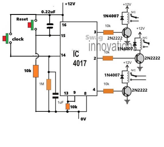
Please make it 1 pulse per second, or 1 pulse per 2 seconds, and then check the response. You can do this quickly by replacing the timing capacitor of your 555 IC with some higher value capacitor…
Or you can remove the 555 stage temporarily and replace the pin#14 of 4017 IC with a push button, as shown below:
And please use the REPlY button to reply under the same thread, so that it becomes easy to track the comments for all of us.
Is using your 16 LED Reverse/Forward Chaser Circuit the best way to have 12 outputs, modifying it to trip relays in only one direction for only one sequence like the 8 output circuit you designed for me above? I tried doing it with your 18 LED light chaser circuit using two IC 4017 but it just locks on one one output from the 555 and pin 3 of the first 4017. Your Youtube video on the dual 4017 is really blurry so it is hard to tell if I missed something.
The 16 LED and the 18 LED chaser both will work, if you build it initially exactly as described in the article….the video may be blurry but it proves the working of the design, so you can use it without doubts.
However latching it after the predefined output may require some thinking…
Hi Swagatam
TL;DR
For my motorbike, I would need a circuit that pilot a LED stripe (so, one output with + and -) with two different currents, the lower one by “default” and the higher one only when a positive input goes high. The circuit should be “immune” to the environment, as the outputs aren’t protected from rain.
Long explanation
My motorcycle has a GIVI case mounted on the back, with LED stop lights made by me.
The case has a 2-pins “touch connector” that, when mounted to the bike, touches a “2-plates” connector mounted on the support. Right now the connector is wired to the bike stop light, and i’ve mounted a cheap chinese buck converter in the case just to regulate the current for the LEDs, to avoid overheating problems.
I would like to use the case lights also for running lights, by reducing the current for the LED (i mean: the same LEDs will have a lesser current for running light, and a higher current when the Stop light are needed).
Given that there’s only two pins available between the bike and the case, i think that the only solution is to move the current regulation in the bike, so a LED driver circuit that is powered by the bike rear light, and that takes the Stop lights as input.
The case is removable, and when it is removed the contacts on the support are exposed: when it rains, they can become wet, so the circuit has to able to handle this.
(an image of the GiVi connector: https://imgur.com/E6DeI4H )
Hi Parduz,
The current consumption is decided by the load, so in your case if the voltages for the load operations are not changing then there’s no need to change the current.
If you could show me the schematic then I could understand the situation better and give my suggestions accordingly…
Here’s one article which shows how the same group of LEDs can be used for brake light as well as running turn light indicator:
https://www.homemade-circuits.com/how-to-make-car-led-chasing-tail-light/
Hello, would you please can you share the circuit diagram of XL6009 DC to DC step up. and the PCB layer design> Thanks”
You can check out this link:
https://www.haoyuelectronics.com/Attachment/XL6009/XL6009-DC-DC-Converter-Datasheet.pdf
How to make motor controller reverse and forward
You can do it in this way:
https://www.homemade-circuits.com/wp-content/uploads/2019/12/motor-reverse-forward.png
thank you sir
I’m wondering if you can help with a problem I would like to solve. I built a small inverter for a vintage radio to replace a B battery 90v . The inverter used 4047 ic and IRF540 mosfets.The radio works extremely well with no EMS. My problem is to use a circuit to automatically shut down the inverter when the radio is turned off, saving battery life. I had a look at one of you designs which used 4 x BC547 and a replay, which I have yet to build. Space is also a problem as some radios have a very small area . I tried a LM358 with 10 ohms in line with the output for current sensing. The problem with it was that the output and input have a common earth which destroyed the IC with 90v on one input. Can you make any suggestions please ? Regards Rudy
Hi Rudy, you can solve this more simply by sensing the inverter input current instead of the 90V output side. The LM358 failed because its input pins cannot tolerate such high common-mode voltage.
A compact method would be to use a small PNP transistor or BC547 relay driver connected across the radio ON/OFF switch or inverter supply line. When the radio draws current, the transistor keeps the inverter enabled, and when the radio is switched OFF the inverter also shuts down automatically after a short delay.
You can also try a reed relay or optocoupler method if isolation is required. Avoid direct sensing on the 90V line with ordinary op-amps.
I’m very grateful for your reply, thank you.
Am I able to send the circuit diagram that a member of our Historical Radio Society designed for comment ? He has a copyright on the auto on/off which I can’t morally and won’t legally copy, it is very effective in it’s operation. If I could achieve the same results I could build about 6 of them for my AC/DC radios. I have no intention to build or sell them commercially. Failing that is there any chance of you helping me designing one with a 6-9v input maximum output of 90v ?
I have built the inverter which works very well, I’m using a 9v to 2 x 120v toroidal transformer.
The transformer is “potted” in an epoxy compound within a plastic housing. Configured with 2 x 120V primaries and 2 identical secondaries which can be wired in either series or parallel.
Specifications
Sec. V: 9+9
Sec. Parallel: 1.1A
Sec. Series: 0.5A
Primary voltage: 2 x 120V AC
Total VA rating: 10VA
Insulation: Class A (105°C)
Magnetizing current: <20mA
Temperature rise: <65°C
Recommended AC Fuse: 100mA
Regulation: ˜20%
Sure, I understand the situation, let me try it, I don’t think it would be difficult for me.
However, the description of the switching pattern suggests that the inverter can never be ON if the radio is OFF. Meaning once the inverter is turned ON, the inverter will check if the radio is also turned ON or not, if not it will simply switch OFF permanaetly,…is that correct??
That is correct, it works extremely well.
OK, thanks, here is the schematic which you can use to solve the application requirement. The Relay coil voltage rating will be same as the battery voltage rating:
https://www.homemade-circuits.com/wp-content/uploads/2026/05/inverter-ON-only-when-radio-is-on.jpg
Thank you for all the trouble you’ve gone to, I shall build it today and let you know
Sure, no problem at all….let me know how it goes.
I built it and it didn’t work. Could please explain how it’s supposed to work and specifically where the 22k connected . You say the 90v supply , is that on the output of the inverter ?
The +90 Volts comes from the radio supply after its switch is turned ON. If the radio switch is OFF, then there should be no +90V available at this 22k input of the transistor. In this situation, if the push button is pressed/released the transistor will remain ON for a couple of seconds through the charge stored inside the 100uF capacitor, and then auto turn OFF the relay and the inverter.
If you press/release the push button again, the same incidence will keep repeating as long as the radio is off (+90V missing at the input of the 22k end). If the radio is ON, then the +90V input will feed the transistor base holding the relay permanently ON, as long as the radio is ON…
The push button is a momentary push to ON switch, meaning it turns OFF as soon as the finger is removed from it.
This circuit is a straightforward design and should start working immediately as intended by you.
Let me know if you still have problems with the circuit…
Thank you for your explanation, very helpful. I will try again possibly tomorrow.
For 800w 1000va (12 dc to 220ac volt) IPS Inverter circuit PCB , already purchased, how many N channel MOSFETs board shall be compatible ?
I have contacted you earlier & got satisfactory reponse.
The number of MOSFETs depends on the transformer current rating and the PCB design. For an 800W to 1000VA 12V inverter normally 4 to 8 N-channel MOSFETs are used, such as IRF3205 connected in parallel.
If your PCB already has fixed MOSFET positions then you should use exactly the number supported by the PCB layout and heatsink arrangement.
I have an invention that you might be wondering about: Dolby sound with two speakers. Can you do it? I’m from Afghanistan. Can you support me?
Sorry, currently I do not have the circuit diagram details for this project…
Hello everyone,
I’m currently working on a project to control curtains, fans, and lamps using a remote control system. My goal is to design a simple and efficient circuit that can wirelessly operate these devices.
I would really appreciate any guidance, especially:
A suitable circuit diagram for this kind of system
Recommended components (e.g., relays, microcontroller like Arduino, IR/RF modules, etc.)
Any tips on improving efficiency and safety
I’m still learning, so even simple explanations or references would help a lot.
Thank you in advance!
Hi, you can get all the required information on this page:
https://www.homemade-circuits.com/?s=fan+remote
I need home automation circuit diagram that control fan, curtain and lighting system. Components values in each circuits. by using the following components: IR remote, power supply 12V DC, buck converter(12Dc-5Dc), IR receiver, ESP32, motor driver(12V Dc), Dc motors, zero crossing detector, opto-triac, triac,
Thank you…I have noted your request in the list, and will try to design it soon, once the other pending request are completed…
Merhaba Swagatam,
tek fazlı değişken frekanslı VFD örnek devreyi çanak vibrasyon makinelerinde kullanabilirmiyiz .yada bu gibi uygulama için önerbileceğiniz bir devre varmı.
Hi Aygun,
if your machine uses a universal motor (with carbon brushes) or a specialized single-phase motor designed for speed control, then a basic single-phase VFD circuit can work.
But for a satellite dish vibration machine which I guess is used for testing how the dish handles structural vibrations or stress….the best and most reliable approach is actually to use a 3-phase motor driven by a VFD with a single-phase input.
Hi again. I have two hydraulic valve packages, type Parker/Olsberg, with 4 valves in each package. Now I’m helping my friend. I built a signal control switch with a changeover relay for the electric control of the valves. The valves are controlled with current control. The problem is when I switch to the second package, the system protests that there is an interruption in the coils. So I have to restart the system again. I was wondering if I could change the relay to something else. Do you have any tips on some type of switcher.
Hi, I do not think the relay itself is the main problem. The controller is probably checking the valve coil current all the time, and during relay switching it sees an open circuit, so it gives the coil interruption error. You may need a “make-before-break” type switch, or an electronic MOSFET/solid-state switch that changes over without disconnecting the load. Can you tell me the coil voltage, coil current, and the relay type you are using? A simple circuit may solve the problem.
Thanks for your reply. Here are your wishes about my problem. The relay I use is from Conrad Finder 40.52.9.024.0001 2 pole alternating 24 volts 8 Ampere. Valve voltage is proportional 24 volts current is about 2 Ampere. The hydraulic valves are called Danfoss PVG 32.
Thanks for the details. I think the Finder relay is the reason for the problem. It is a normal break-before-make relay so during switching both valve packages are disconnected for a short moment. The Danfoss controller then sees an open coil and gives you the interruption error. I think you will need a make-before-break switching circuit, or an electronic MOSFET/solid-state changeover which keeps one valve connected until the other is connected. Another way could be to check if the Danfoss controller has a setting to disable the coil monitoring during switching. That may also solve the problem.
Do you have any alternative to another 2 pole changeover relay, possibly from Conrad? Greetings Göran
A 2-pole changeover relay is simply a DPDT (Double-Pole Double-Throw) relay. On Conrad, you can find them by filtering for “2 changeovers” (2 Wechsler).
Here are three alternatives they might have:
Finder 40.52 Series (8A rating, very common)
Omron G2R-2 Series (5A rating, industry standard)
Panasonic JW2SN Series (5A/8A rating, compact)
Just make sure to select the correct coil voltage (like 12VDC)
I’ve been asked to fit 3 remote leds to be fitted in parallel with existing 12v fuel gauge to indicate empty, half full, full. The supply voltage will be taken from the fuel sender unit. The value for the variable resistor in sender is 3 to 410 ohms.
Sure, you can add the LEDs in parallel with the existing ones through a series resistor whose value should be same as the existing LED series resistor’s value…
thanks for your prompt reply,i’ll give it a try
Can you introduce me to an FM circuit that I can implement in both ltspice and ctrl200? Thank you for your guidance
Sorry, I have no idea which FM circuit could be simulated on those simulators…however i think a BJT based design can be simulated on all standard simulators…
Which FM circuit are you referring to, transmitter or radio?
Good afternoon, Mr. Swagatam. Could you please post a circuit for connecting two lithium batteries for use on an electric bicycle with a hub motor? This would increase the range. When one battery runs out, the other one kicks in.
Thank you very much.
Hi Giuseppe,
Do you want the circuit with charger circuit, or only the batteries with a changeover stage? Please let me know I will quickly design it for you…
I’m trying to modify this circuit a bit and am having issues. Look at Figure 18 here. (I tried to copy and paste but it wouldn’t work).
https://www.homemade-circuits.com/wp-content/uploads/2026/08/555-flasher.jpg
I need a low current draw flashing circuit.
I would like to replace LED1 with 3 blue LEDs in series (so 6 to 6.6V drop). I’d rather have them a bit dimmer than risk overvoltage failure.
I’ve built the circuit several times and expect I am toasting the IC chip.
I’ve been using a 1.6K resistor for R3. I expect this is the issue??
The LED’s are not blowing, but not flashing.
I built one circuit using fairly large variable resistors for R2 and R3. It works intermittently. It acts like it has a cold solder joint (yes I was building on a circuit board). Function depends on orientation of the board.
In my younger years this would have been a walk in the park.
I simulated your circuit with 12V and 3 blue LEDs in series with a 1k series resistor (R3) and it worked perfectly.
Please try changing the R1 to 18k, R2 to 150k, and C1 to 10uF, this will give you a flashing rate of around 1 second ON, 1 second OFF. If you find your 555 getting warm or hot at 12V, then definitely your 555 IC may be faulty or not the original make…
THANKS for your input.
I have a breadboard arriving tomorrow to build test circuits on (enough soldering things up to test).
I would prefer shorter ON time, and a slightly longer OFF time. This circuit is to simulate the flashing LEDs of a car alarm system.
The voltage will often be above 12V since alternators routinely put out up to 14V. Battery voltage while not running is normally above a true 12V, more like 12.5V. I don’t know what that would do to the values of components.
The low current draw was desired to not discharge the car battery over extended periods.
Sure, no problem….for the component adjustments, you can try the following software….Try to keep R1, R2, on the higher side, while the capacitor lower.
https://www.homemade-circuits.com/ic-555-timer-astable-circuit-calculator/
The chips I am using are definitely cheap knockoffs. 10 of them were $9. (10pcs ICM7555 General Purpose CMOS Timers Chips IC,DIP-8)
I wonder if that will be a problem.
10 nos at $9 is too costly for Indian standards, you can get original chips much cheaper than this in India…
However, if it is getting hot at 12V and LEDs at pin#3 with resistor, then certainly the ICs could be malfunctioning…
I have a water pump bought cheaply at a nearby electronic stores. Its voltage and amp rating is not known but it runs nicely at 7.4V 3A. However, every time I need to start it, I need 16.8V to kickstart it and then I can run it with my 7.4V Li-ion pack. Is there any circuit that makes sure that the motor doesn’t need the initial 16.8V of power to start up and it can run with 7.4V throughout? Thanks in advance
Actually the pump is taking 16.8V kick just to break that initial tight motor friction. Best solution is put one cheap MT3608 or XL6009 boost converter module set to 16.8V, along with one simple 1-second delay relay or 555 timer circuit. So when you switch ON, then it gives 16.8V boost for just 1 second to kickstart the motor, then relay immediately switches line to direct 7.4V battery pack for normal running!
Is it possible you share the circuit diagram here
You can try this configuration:
https://www.homemade-circuits.com/wp-content/uploads/2026/08/starting-torque-to-motor-changeover-circuit-diagram.jpg
On my old motorcycle, I’ve added a piezo beeper on each of the front turn indicators: that’s allows me to not forget them on. Puttin one on each was the easyest way to make it works.
I’ve done the same on my new one, but this new bike flashes the turn indicators to signal that the keyless system is engaged, resultin in a lot of noise.
What would be the simplest, smaller circuit to make a beeper sounds when one indicator is on, but not when both of them are on?
I think the easiest way is to use only one common buzzer for all the indicators, meaning if any of the indicators is turned ON, the buzzer sounds. This will also solve the noise issue during the keyless retry. What do you think?
hi sir,,it’s MdKen,,than you so much..
pls can you help me with a high end 9v powered 3band eq onboard preamp circuit design I can put in my ibanez sr505 bass guitar…I bought a it cheap but it was sabotaged …
the guitar uses 2 passive pickups
Hi Md.
You can try the first circuit from the following article:
https://www.homemade-circuits.com/10-band-graphic-equalizer-circuit-for/
For further doubts, you can feel free to comment under the above article..
hello goodmorning, goodevening, and good afternoon in anywhere you can saw this message, I’m one of this class and am glad to be here.
my greetings also goes to our boss may God bless him.
please sir I need a well drawn circuit diagram for inverter oscillator project with a voltage regulator. please 🙏 I will be so glad 😊 if I can have it.and that reminds me sir that the ic must be sg3524n or sg3525 ic
Good evening Michael,
If you search for “SG3525” in the top search box, you can get many good options which will fulfil your requirement…
alright, thanks boss I will do that
Hello! Do you have any good RF power amplifiers for the 35 MHz band, approximately 0.5 W, operating voltage around 12 volts?
Hi, I think you can get a 30 MHz design in the following article, which might need some modifications to be able to amplify a 35 MHz signal:
https://www.homemade-circuits.com/wideband-amplifier-circuits/
good day sir, I hope all is good, please sir I need your help I need a good working Sg3524 with feedback oscillator for inverter 12volts system thank you very much sir
Hi Solomon, you can try the concepts explained in this article:
https://www.homemade-circuits.com/inverter-circuit-with-feedback-control/
Goodday sir, I want to ask that is it compulsory to put 6capacitor in parallel to make a input filter for 12v system using SG3524N inverter oscillator?.
No, you can use any number of capacitors as long as the total capacitance and ripple current rating are enough to handle the input load and switching spikes of the 12V inverter. Multiple capacitors are usually just used in parallel to share the ripple current, reduce equivalent series resistance (ESR), and fit the physical space better.