In this post I have explained a few miniature inverter circuits that can convert 1.5 V to 220 V or 3 V to 220 V or 6 V to 220 V. All the designs employ a single PNP transistor and transformer, connected in the feedback mode for generating the oscillations.
1.5 V to 220 V Inverter Circuit
The mini inverter circuit demonstrated in the following figure can produce a highest AC output of 220 volts if it is powered through any battery between 1.5 V and 6 V battery. It employs a TIP2955 power transistor forming a Hartley type oscillator with the transformer.
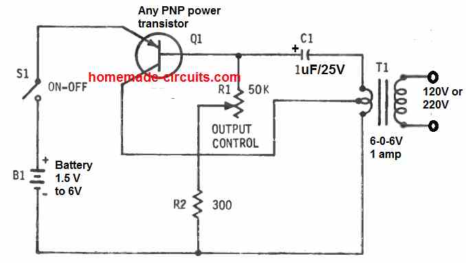
The center tapped 6.3 v winding of a small iron core transformer (T1) works like a center feedback type of coil for this oscillator. With a 6 V battery (B1), the highest current drain is around 80 ma. The 50k 10 watt wirewound potentiometer (R1) adjusts the no-load DC output between 2 V and 220 V volts.
In this inverter design if R1 is substituted by a 200 ohm 10 watt wirewound pot and R2 replaced with a 20 ohm, 1 watt resistor, battery B1 specifications could be minimized to 1.5 V., and then the circuit work like a 1.5 V to 220 V inverter circuit.
The maximum drain from the battery at 1.5 V supply will be roughly around 100 ma. R1 will alter the DC output between 60 and 80 volts, in the absence of a load.
3 V to 220 V Inverter Circuit
The next 3 V to 220 V inverter circuit is designed to work in a blocking oscillator mode having an operating frequency set at around 400 Hz. The transistor used can be any PNP power transistor.
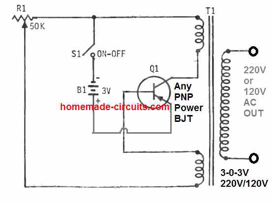
The center tap transformer can be any standard step down transformer. This transformer provides the feedback and the voltage boosting both together.
The connections of the two low voltage windings of T1 must be configured correctly with the transistor, otherwise the inverter may fail to work, and begin heating up.
The 50 K potentiometer is a wirewound variable resistor (R1) which must be appropriately set to get reliable oscillation and the maximum voltage output. This 3 V to 220 V inverter circuit may draws around 70 ma from the 3 V battery (B1).
6V Inverter Circuit
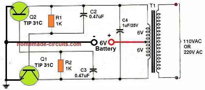
The inverter circuit seen above is built around a straightforward astable multivibrator, which pushes and pulls its output via the secondary of a center-tapped, 12-volt step down power transformer.
The circuit is powered by 6 volts of DC from four AAA batteries. If T1 is swapped out for a 220 VAC transformer and its secondary is attached to the terminals of the fluorescent lamp, it may have adequate power to illuminate bulbs up to 50 watts.


Questions & Answers
sir, namashyate I want to make my own transformer less circuit to charge a 18650 lithium ion battery please suggest and send me a suitable circuit diagram please.
Atul, transformerless power supply using capacitor can be dangerous, since it will be non-isolated and prone to lethal electric shock, so I don’t recommend it…
sir, then please suggest me any homemade circuit to charge 18650 3.7v,3000ma li-ion battery.
Atul, if you want to avoid heavy transformer, then you can try the following SMPS design, and replace the 5V zener diode with a 4V zener diode:
https://www.homemade-circuits.com/220v-smps-cell-phone-charger-circuit/
Good day sir please sir am in need of a good working 3v to 220v ac circuit please sir it is urgent sir
Samson,
You can try the 6V inverter circuit from the above article and use it with a 3V supply. Replace the transformer with a 3V-0-3V transformer.
….Also make sure to replace the transistors with TIP142….
Boss, the transfer to be use must has 3 input and 2 output wires?.
The common transformer I got has 2 input and 2 output wires, is it useable.?
I which circuit do you want to use your 2 wire transformer?
This same 1.5v to 220v
That inverter cannot be built with a two wire transformer, it requires a center tap transformer.
Alright boss, I will try an get it, thanks
What best of PNP transistor to be use, I want to use 12v input and output 230v that can power tv and fan??
For TV or fan you will need a 10 amp transformer, a TIP36 transistor and a 10 Ah 6 V battery
Thanks boss.
I will try it out.
Happy to meet myself in this group
It’s my pleasure Kamkooltech.
good morning,
could the switch S1 be replaced with a timed on-off -on circuit to make it fully automatic in the first circuit, also i just need the low voltage ac output so don’t need to use the transformer.
thank you for any help.
Alan
Hi, what kind of timer do you want to use in place of switch S1?
Hi a simple timed on off on electronic circuit. Would you have any suggestions please!
on, off, on…do you mean an oscillator circuit with an alternating ON–OFF output? In that case you can use a 555 astable oscillator circuit with a relay…and then replace the S1 switch with the relay contacts.
thanks for your reply. i would need the circuit to stay on for about 6 hours then off for about 18 hours and then on again automatically. it is to supply about 5 volts ac from a solar charged 3.7-volt li-ion battery. not sure if this is possible though.
Alan
OK, in that case the timer circuit would look more complex than the inverter circuit. Moreover, except the last design above, none of the other circuits would work without a transformer.
For the timer circuit you would require the following design:
Simple Programmable Timer Circuit
Sir can I ignore the use of 10k potentiometer?
Hello Biswajit, are you referring to the 50 K pot? The pot determines the frequency of the inverter output.
please I need your help, I have a 6v, 6w, 1000mA, solar panel I want to use it to charge my phone but If i connect it to the phone it shows me “OVER VOLTAGE” what can I do please ?
Please use a 7805 IC for regulating the charging voltage to 5V and then check the response.
tv woking can dc12v in 23vac inveter circuit
No 12V TV cannot be used with a 23V AC supply
Good day, Mr Swagatam,i want to know if i can use transistor TTC5200 series to build my 1.5V inverter with that your circuit for 1.5V above. Thanks for the training i really appreciate your efforts and time to help humanity.
Hi Jacob, it cannot be used for the 1.5 V inverter since it is designed for 230V operation, and therefore will work inefficiently at 1.5 V or 3V. You can use 8550, 2N2907, BD140 etc
Thank you Mr Swagatam, i will try those you told me to use.
You are welcome Jacob!
1.P LEASE SIR CAN THIS INVERTER 1.5V TO 220V POWER AC BULB, LIKE 5WATT? AND CHARGING OF PHONE?
2. CAN I PARALLEL THE BATTERY IN ORDER TO LAST FOR HOURS?
Yes, both the things are possible..
THANK YOU SIR FOR THE QUICK RESPONSE. BUT SIR I COULD NOT FIND 50K 10WATT POTENTIOMETR. PLEASE CAN ORDINARY 50K POT WORK? IF NO, WHAT IS THE WAY FORWARD SIR? MATERIALS ARE VERY SCARCE HERE. THANK YOU SO MUCH SIR.
Hello Godspower, yes any any ordinary pot will work, even 47 k pot will work.
Thank you sir
Good day Mr Swag thank you so much am really greatful your site has really helped me a lot. I have a question regarding the first circuit 1.5v to 220v mini inverter
1. What other capacitor can I use to replace 1uf/25v?
2. I have 12-0-12 500mA transformer, will it work sir?
3. Will bc557 pnp transistor work?
Thank you sir
Hello Godspower, The capacitor decides the frequency, you can try other capacitors but that will change the output frequency of the inverter.
Transformer primary winding voltage must be identical to the battery voltage value.
BC557 will handle and produce less than 1 watt output power