
This circuit is basically a H bridge inverter where two IC IR2111 are working for driving four MOSFETs that are connected in H bridge way. We also see that there is a overload and over current shut down using BC547 small transistors. So what happens is that we can run a load with AC waveform […]
Inverter
Modified Inverter Circuits using 4049, 4093 ICs

The following inverter designs are unique modified sine wave inverter concepts designed me. The entire unit along with the oscillator stage and the output stage can be easily built by any electronic enthusiast at home. The present designed will be easily able to support 500 VA of output load. Let’s try to understand the circuit […]
Adjustable RMS Modified Inverter Circuit using BJTs

A very interesting circuit of a RMS controlled modified sine wave inverter is discussed in this article which incorporates just ordinary transistors for the proposed implementations. The use of transistors typically makes the circuit easier to understand and more friendly with the new electronic enthusiasts. The inclusion of a PWM control in the circuit makes […]
Modified Sine Wave Inverter Circuits using IC 555 and 4017
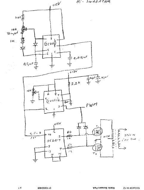
When an inverter with square wave AC output is modified to generate a crude sinewave AC output, it is called a modified sine wave inverter. The following article presents interesting modified sine wave inverter designs with exhaustive descriptions regarding its construction procedure, circuit diagram, waveform output and detailed parts lists. The designs are intended for […]
IR2111 H-Bridge Inverter Circuit with Soft Start

Here we see this circuit diagram which is full H-Bridge using 4 power MOSFETs and 2 IR2111 high side driver ICs. That means this circuit is for making full bridge inverter which converts DC into AC. Power Supply Part We have +600V DC at top rail, written as +600V max. And ground (0V) at bottom. […]
Solving Inverter “No Load Auto-Shutdown” Problem
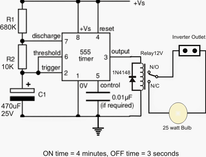
In this post I have explained how to trick an inverter’s “no load auto-shutdown” feature through an external circuit so that the inverter may be kept running even with minor, below permissible loads at the output. The idea was requested by Mr. Em. Technical Specifications Thanks for your prompt responses and guidance. I was wondering […]