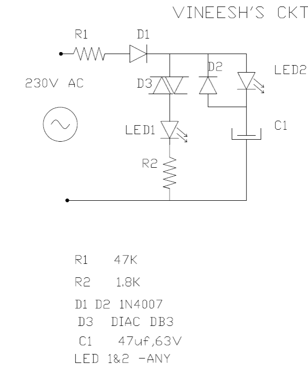
The following triac/diac based mains operated LED flasher circuit which is actually an astable multivibrator circuit utilizes only a diac and resistor arrangement for implementing interesting wig wag flashing of two LEDs.
The simple 220V flasher circuit was shared with me by Mr.Vineesh, who is one of the keen followers of this blog.
I would like to present the email that was sent to me by Mr.Vineesh.
The Circuit Objective
Dear sir,
Hope you remember me. I am not an electronics engineer,working as manager in a company, dealing basically with Tool & Die Engineer, but self studying electronics for past 12-13 years,and have designed and made many simple projects of my own.
Some of them are marketed too actually this entire ckt attached is not my idea.
I have gone through 230V blinking LED circuit in some sites. I just converted it to alternate blinking circuit working fine for last 2-3 months continuously (used green bright leds).
I know very well no need to explain the working of ckt. But just given 2 lines because if I am wrong in theory, you can correct me.
Practically crkt is working well. While cap charging, led2, (series with cap) lights. DB3 get less than 30V while cap charging and does not conduct.
After full charge of cap, diac conducts and led1( series to diac) lights, and cap discharge through 1N 4007 ,that time LED2 light get dim, which gives alternate blinking effect.
1.8K Resistor series to led1 is more than the requirement, but given for matching the light intensity with LED2 all my ckts are drawn in note books, just selected one small ckt from that which is easy to draw in CAD & and convert pdf bcoz don't want to send shabby hand drawn drawings.
Thanks & Regards
vineesh
Analyzing the Circuit
Dear Vineesh,
Your explanation is absolutely correct, and the LED flasher circuit is also very good, it can be well modified for ganpati, diwali, Christmas or for other similar decoration purposes. Good effort.
Thanks and Regards
Swagatam


Comments
Dear Sir Swagatam
Hello. Thank you very much for your so good and practical circuit which with no problem came on and began blinking as soon as I plugged the assembled circuit entering into 220 volt AC; but, after I put the associated parts together in order to accommodate it inside the line cabinet tester with 2 pieces of soft springs in front of and back of it and plugged the screw driver into the line socket and touched it’s handle, no blinking occurred. Then, when I inserted the other side of a wire that had been connected to the handle of it, into the ground hole of the main’s socket it began blinking again. I think ( and I hope that I am wrong ) a power ground is needed for the circuit to work and this project could not be substituted for neon lamp ones.
once again I thank you for being so kind and good.
Never forget your kindness
very truly yours
Nassim
Thank you Dear Nassim, yes we complete forgot this point. The above circuit will require both phase and neutral, or direct earthing to function, it cannot be activated through our body grounding, therefore it cannot be substituted for a neon lamp based circuit.
Dear Sir Swagatam
Hello. Thank you very much for your proposing substitution circuit, and the link related neon lamp as well. I knew that it was not yours and that it has been working for 2 to 3 months as he had said. I am still so astonished why this very simple circuit did not work. I wish you were free enough to do that yourself. I tried it as I thought that it would be possibly a better substitution ( with it’s 2 blinking LEDs) for commercial neon line testers which emit little light and we can hardly see their light where there is sunshine.
I will try your circuit, accommodate it inside a screwdriver back side plastic enclosure and and will tell you very good man the result soon.
Best regards
Nassim
Thank you Nassim, In my free time I will surely check the circuit, I hope the new circuit works for you!
Dear Sir Swagatam
Hello. Hope you are fine. I think I am the only man who has tried this circuit so far and the only things that I can tell are as following:
1. LED2 remains on with low light without blinking.
2. LED1 did not came on. I substituted R1, D1, and D3 with new ones for 4 times but LED1 remained off yet.
3. The voltage drop after D1 was 11 volt and when I removed D3, LED1 came on. The voltage and the current drop on LED1 is near 3 volt and 5mA. No blinking occured by none of LEDs.
A.Would you please do a favor and solve the problem?
B. Since I have decided to use the circuit as a shining and blinking line detector, how can I increase the LEDs light so that they carry about 20 mA of current?
Thank you in advance for your response.
Best regards
Nassim
Hello Dear Nassim,
This circuit was not designed by me, so I am sorry I can’t troubleshoot it for you. However as you can read in the article the person who submitted the circuit has already tested it and he has tested it for 2 to 3 months without problems, so I am not sure why it is not working for you.
Alternatively you can try the following idea:
If you are still having difficulty in making this, you can try a simple neon flasher concept instead, as explained in the following article:
https://www.homemade-circuits.com/neon-lamps-working-and-application-circuits/
Sir engineer Swagatam
Goon night
Can I use 47 uf 50 volt for C1 instead of 63 v? if not why? will it explode?
Thank you sir
Bye
Hello Mike, 47uF/50V should also work, you can try it…it will not explode due to the presence of the 47k resistor
Dear Sir Swagatam
Hello an thank you so much for your prompt reply which made me very glad but do you mean that I should add a triac to the circuit or this word is mistakenly used instead of diac?
Wish you the best
yours truly
Nassim
You are most welcome Nassim,
yes you are right, it is actually a diac which I mistakenly mentioned as a triac…so now definitely you can accommodate the whole system inside a screwdriver back side plastic enclosure.
Hi dear Sir Swagatam
Hello. Please tell me is it possible to put the entire circuit inside the plastic part of a screw driver and connect the enterings of the circuit to both metallic parts of the screw driver in order to use it as a mains phase detector, like commercial ones with a resistor and a neon lamp.?
Wish you the best
Nassim
Hi Nassim, yes it is possible to put the whole thing inside a suitable line tester cabinet, however, a triac is involved in the circuit, which means that the plastic portion behind the tester must have sufficient space to accommodate the triac and the associated parts.
Hello i really want to appreciate you, you indeed my hero when it comes to electronic. sir while i was going through the comments i noticed you said for 24v the ic741 should be replaced by lm321 and for another person you said he build the last circuit as it is for 24v please my question is can the last circuit work for 24v without modification because i have bought the components for it waiting for your reply before i start building thanks and best regards
thank you, I think you posted under the wrong article.
however a IC 741 cannot run with a 24V supply so a LM321 is the recommended IC for a 24V supply
Dear Swagatam,
I need to do one array with 60 leds for my AC command of my car.
The 48 3mm blue leds use 3.2V 20mA each and the other 12 red leds need 2.2v 20mA each.
The problem is, my car use 17v with engine on and 15v with engine off.
I made a schematic pcb with L7808CV voltage regulator, this regulator can imput 0-32vin and following datasheet I left 8v stabilized with the capacitor. Following datasheet I left 8v stabilized out but it is heating up too much and do not have space for heatsink and it is heating up too much . Is there any alternative to this pcb with 8v stabilized without heat so much?
Thanks for any help.
Denys
…sorry I missed the 3,2V LEDs, OK you can configure them in the following manner:
make 16 strings of blue LEDs having 3 series LeDs and a series 390 ohm 1/4 watt resistor in each string
and 3 strings of red LEDs having 4 series LEDs and a series 270 ohm 1/4 watt resistor in each string
Dear Denys, A voltage regulator may not be required for 20mA LEDs
Let's assume the minimum supply level to be 12V, and max to be 17V, you will need to make 15 strings of LEDs having 4 series LEDs in each string along with a 270 ohm 1/4 watt resistors with each LED string. Connect all these strings in parallel with the supply input.
That's all, the LeDs will be safely lit with absolutely no heat.