In this post I have explained a simple IR based remote controlled night lamp timer circuit. The idea was requested by Mr. Raj Kumar Mukherji.
Technical Specifications
Please provide the component values and the modified circuit if:
a. the circuit is made to work from 4.5 volts or 5 volts
b. the relay is replaced with a 5mm LED
c. the circuit is triggered by TSOP1738
d the delay time is set for 2 mins max
This is for an old person in my locality. He wants a low cost portable light which he would turn on
remotely for a brief period at night and the light would get turned off automatically. He has to get up at night to drink water etc and he does not want a night lamp to be on the whole night or to operate one from the mains power. The best idea that came in my mind is to use the transistorized timer circuit in combination with a TSOP1738 and using 2 or 3 AA cells.
Thanks and regards,
Raj Kumar Mukherji
The Design
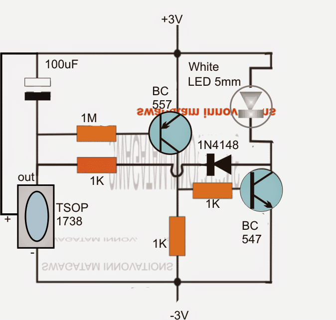
The proposed remote night lamp timer circuit can be visualized in the above diagram and understood with the following points:
The IR sensor TSOP1738 responds to an incoming IR signal from a suitable IR handset such as a TV remote or similar, and produces a logic low at its pin labelled as "out". The directed Tx signal could be momentary, probably for a fraction of a second for initiating the triggering response in the circuit.
The above action instantly charges the 100uF and also switches ON the BC557. This correspondingly turns on the BC547 and the LED.
The stored charge sustains the switched ON position for a certain time period determined via the selected values of the 100uF capacitor and the 1M resistor. These may be altered, experimented for acquiring any desired time delay for the LED illumination period.
The 100uF slowly starts discharging via the 1M resistor and the base/emitter of the BC557 until it becomes too low for the transistors to hold the conduction, the LED consequently is also switched OFF as soon the RC determined time is elapsed.
The 1K and the 1N4148 diode ensures a complete discharge of the timing capacitor 100uF each time the LED is switched OFF, so that the new cycle is able to begin with a correctly discharged capacitor, for executing consistent time delays, with minimum errors.
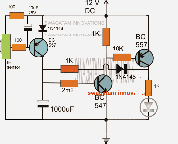
The above design can be upgraded as shown below for getting improved response:


Questions & Answers
Cool
thanks!
I want you to be realistic sir, can u refer me to an inverter circuit on your blog that can power a laptop and a 15watt cfl bulb at the same time I want a cost effective one sir. I know I can search for it myself but I want you to choose for me the load won't be too much as u can see
Sir I want to add below circuit with this one but I have some confusion to connecting with IC pin. Can you check and conform . I bought all parts and dont want to bear burn of any part.
https://www.homemade-circuits.com/2011/12/how-to-build-simple-hi-efficiency-led.html
s1.postimg.org/n8dgq7fen/IC_4049.jpg
Ram, the diagram is clearly shown in this post:
https://www.homemade-circuits.com/2011/12/how-to-build-simple-hi-efficiency-led.html
please do it exactly according to this diagram and nothing will burn.
I have confusion in pin 2 and 5 , both are connected together then need to connect with resister ?
It's perfect…no resistor is required there.
hi swagatam,
i got a problem with this circuit, the circuit turns on automatically when its powered and stays on… i powered it with a 4v 500mah lead acid battery.. what could be the problem ?
Hi Bibin,
remove the TSOP sensor and check.
If it still switches ON then definitely the problem could be somewhere in your design because without a ground signal to 1M the circuit can never switch ON.
If it's not the case then the problem could be with the sensor configuration, it may be leaking some ground to the 1M…which can be rectified either by adding a zener diode in series with its OUT pin or reduce its supply voltage for the same
or through some other alternative method which will eliminate a ground to 1M until the sensor is actually activated.
Hi swagatam,
i replaced the tsop sensor with a new one.. now its working properly..
thankyou swagatam….
That's great Bibin, thanks for the update.
want this ckt to drive about 500mA at 3.3 volts, biasing with 4 v battery. My point of view is to add a tip122 as buffer for higher current application.. is it right??
yes that's correct!
any suggestion for connection.
simply replace BC547 with TIP122
What could be its remote swagatam ??
you can use any TV remote handset…
oh Thanx bro.
SIr plz add one very simple circuit for IR Transmitter too which can operate on button cell. Then we can use it for many useful applications.
Ram you can refer to this article for the Tx circuit:
homemadecircuitsandschematics.blogspot.in/2013/03/simple-reliable-infrared-ir-remote.htmlmotion detector on online
I guess its simply a IR LED with Resister in series as per battery ?
Just a 10 ohm 1/4 watt resistor will work in series with 3v button cell. Use a push button to blink the ir.you are done.
Hi Swagatam,
I just love your circuits and have just finished drawing (in ExpressPCB) and etched some of them. Now I am looking forward to build them.
Could you provide me with a schematic for a timer circuit with presets and 7-segments?
I need a timer circuit where I can adjust the time from 0 to 999 seconds.
When adjusting the time preset the 7-segment shall show the preset time.
When time is running the 7-segments shall show the remaining time. When the time period has elapsed a relay should be activated.
Also needed a reset button to start all over.
Thank you,
Henrik
Hi Henrik,
0-999 seconds timer circuit with preset display is possible but showing the remaining time looks difficult,….. if i happen to crack it I'll post it in my blog…
Hi Swagatam,
Thank you for your reply.
Please don’t waste too much of your time on showing the remaining time. I wasn’t aware of the difficulties by showing the remaining time. I would be happy for the circuit even without showing the remaining time.
Thanks Henrik,
I'll try to post it soon in this blog, please check back after a couple of days
Hi Henriks,
I tried to figure out the design, it could get quite complicated with 4 to 5 ICs and many passive parts due to the inclusion of the time display module,
Hi Sir,
I am Raju, I want LED Lantern circuit with Remote operation(12 Led's, 8mm, 4v 1500ma Lead Acid Battery) any suggestions.
Hi Raju,
you can connect all the LEDs in parallel with the battery terminals, and for remote operation you can buy any single relay RF remote control unit and wire its relay with the LED
Hi Swagatam,
I have just tried this circuit Remote Controlled Night Lamp Circuit with Timer.
It works great except that the LED turns off almost immediately.
I have tried to change the resistor (1M) to smaller ones (10K) and changed the capacitor to bigger ones (2200 uF). It helps but still the LED is lit less than 1 min. My LED is a warm white LED.
Do I need to include a timer circuit like the 4060 IC to have the LED lit for 2-3 minutes?
I have also tried to change the voltage from 3 to 4.5 V. Same result.
I am impressed that the distance is more than 5 meters with a TV-remote controller.
Now is it possible to change the circuit to react on a certain button to turn on the white LED and another button to turn on a red LED?
Again thank you very much for all your great circuits. It is really a pleasure to build your circuits. They work and you schematics are much easier to read than most other.
Thanks Henriks,
THe 1M resistor is also directly responsible for generating the time delay, reducing it to 10K will drastically affect the time delay, on the contrary increasing it will ensure longer time delays.
Try 1M and you will see much difference in the time interval for which the LEd stays ON.
4060 is a classic timer IC and it can be used for advanced timer applications, so you can always try it out for enhanced ejects.
Thanks for your reply,
Is this CIRCUIT is not work for LED Lantern? If not What changes should i do.
please explain your application in detail…
…..no the above circuit is not for remote ON/OFF toggling operations…
Dear,
Suppose the above said circuit described by you is used to work the moment button pressed by the remote, the rc time is say 2min mean the light will glow until rc time elapses.
But can the circuit be switched off in between by pressing the remote button once again?
Dear Sherwin,
the above circuit has been designed as per the mentioned request, it's timer based and will not switch off with the remote control signal.
Dear, one more thing,
Input signal to tsop1738 should be exact 38KHz or if there is few khz more or less will it not work??
a TV remote will have this frequency in its signals.
Ok,
To control a relay from the above circuit, and using 6v to power the circuit
could i use mje3055 and mje2955 transistors in place of above to-92 npn and pnp types.
should i change 1n4148 to 1n4007??
what is the best and accurate way of controlling the delay time of connected load,
any further component changes by any chance??
I will build this in coming days time,
so please help me.
Thanks.
The shown BC547 will be able to handle a small relay easily, so no need of changing it, if the relay has higher coil current in that case a 8050 or a 2N2222 can be tried in place of BC547
sir, how can i modify this circuit to run led light contieously until switch off with remote
thank you sir
Manjunath, the above circuit is designed to run continuously until switched OFF with the remote handset.
sorry, No, the above circuit will do the opposite actually, for implementing your application the circuit will need to be changed entirely …using a latch configuration.
sir in above circuit was both transistors are BC547
1) bc547 npn
2) bc 547 pnp
was this right sir
Really sorry sir I didn't refer image properly.
The transistor is bc547 npn and Bc557. Pnp
again sorry
and thank you very much for your cooool answers
OK manjunath, no problems!
Sir does any IR reciver works as usual . Or should i use only TSOP1738 .
now I had used simply an IR reciver it does not contain any number. But not working.
any 3-pin type IR sensor might work, however TSOP series sensors would be more appropriate for perfect operation.
Sir as I switching on the circuit. LED glows. if I operate remote slightly LED blinks that's all it won't switch off.
Thank you sir
Manjunath, which circuit are you referring to? please explain how you have build it
sir , my above question was about
Remote Controlled Night Lamp Circuit with Timer circuit
thank you.
remove the TSOP and then switch on the circuit and check the LED response, keep the 1K, 1M, and 100uF disconnected from the ground when you switch ON power.
The LED should not switch ON…..now just momentarily touch and remove the 1K, 1M, 100uF junction to ground….now the LED should illuminate and then shut off after sometime.
confirm the above first.
sir, if i wrong connected the transistor,or tsop or any IC's in any other circuits would damage that perticular components or any other related Components .
and that wrong connected components can be reused or reconnected or waste.
* sir but in this circuit ( Remote Controlled Night Lamp Circuit with Timer circuit ). I need pinout diagram of both bc557 and bc547 . that i confused to connect.
yes it can definitely damage or destroy the particular component, and once damaged it will need to be thrown of, can never be used again.
for BC547/557, the right hand side pin is the emitter, center pin is the base and the left side is the collector….keep the transistor printed side facing you and its pins downward while confirming this.
Sir I changed all components that had wrong connected except IR sensor and rebuild circuit. Now it led glows as soon I switched on circuit.
And if remote operates led switchs off for 3 to 4 seconds and then glows.
Was this malfunction may be due to IR sensor . Or other.
Thank you very much.
manjunath, the LED should not glow when switched ON…check the circuit first by removing the sensor, that is without connecting the sensor…..
On the day of "GURUPOORNIMA"
guru swagatam sir ko pranaam.
thank you shishya Manjunath!
sir
Any method to find out the , negetive,positive,and out terminals of any IR sensor's with multimeter or any method
thank you sir
No, there's no way of identifying through a meter or any other similar method….you'll have to refer to its datasheet for the details.
Sir I made another circuit of Remote Controlled Night Lamp Circuit with Timer circuit
I works but the LED glows only for 2 second s
so I changed 1m resistor to 4.7 k and capacitor to 1000uf but now LED glows for 3 to 4 seconds only and if I keep pressed
remote button for while LED will glows little more time. What may be the fault sir
and also the ir sensor which I have with name mentioned at top "vire" 1= out 2=ground 3= VCC.
Thank you sir.
Manjunath, increase the value of the resistor, because the value is directly proportional to the delay period, try a 100k resistor.
I'll try to update a modified design soon, which will be able to produce better results.
Ok thank you sir
sir I had changed resistor value by 100k.
but now also the LED glows for 1 or 2 more seconds as earlyer
sir please modifie design
thank you
manjunath, please make the following circuit first:
https://www.homemade-circuits.com/2014/11/long-duration-timer-circuit-using.html
replace the relay with a LED/resistor.
replace the push switch with the emitter/collector of a BC557 transistor (emitter to positive)
connect the base with the out pin of the IR sensor via a 220 ohm resistor….rest you know how to proceed
Sir,
Replacing push switch mean should I join another bc557 in the place of push switch.
And replacing relay with led with resistor was resistor value may be 220 ohms .
Thank you very much.
yes replace the switch points with a another BC557 emitter/collector
yes resistor 220 ohm will do
sir
i feel sorry to disturb you again and again.
i made the circuit (https://www.homemade-circuits.com/2014/11/long-duration-timer-circuit-using.html)
but i fail to be success. the IR sensor got hot, that means i had wrong connected. sir please can i expect modified diagram of this circuit.
actually i had repalced switch with bc557 (emitter to positive, base to IR out with resistor. and connector to negetive) and the capacitor stage that i had confused but i connected to positive side of capacitor to junction bc557 emitter and 12v positive, and negetive to junction of bc547 emitter,led negetive.
thank you very much sir
manjunath, I have posted the updated design, please check it out…
Thank you very much sir.
Sir
In updated design circuit
Which is out , positive and negative of IR sensor
Thank you.
the center one is the output…upper one is the positive, and the lower one is the negative.
good day sir
in the modified diagram supply voltage shown is 12v . do i need to use 7805 ic to feed 5v to tsop or can i connect 12v directlypls advice
john
John, I forgot to connect a 7805 for the sensor…it must be included for the sensor module.