Are you looking for free circuit diagrams, project ideas, and solutions? Are you interested in getting personalized help with an electronics project you're having trouble with?
Feel absolutely free to contact me through the comment box below the articles for getting quick solutions to your queries. I'll try my best to get it done for you absolutely FREE!
For submitting schematics or circuit diagrams you can send them to the following emails addresses.
Email ID
homemadecircuits
@gmail.com
Work Address

Questions & Answers
Hello-
I enjoy your website very much and have come across it a few times and so finally I have subscribed.
Something that has interested me over the years is the Tesla pancake coil. It has all kinds of unique features and uses but the one that I like best is the supposed overunity capability of this coil. Some say if you find and use the resonate frequency of a pancake coil then more power will come out than went in. Ya, not supposed to happen right? There are more than a couple of people on the internet who demonstrate that effect or at least seem to.
So I am sure you have heard of it too and I am wondering what your thoughts about it is or perhaps you have already experimented with these interesting coils?
Thanks in advance!
Hello Pierre, Thanks for subscribing and for the kind words!
The Tesla pancake coil is an amazing piece of engineering. Its flat spiral design maximizes internal capacitance, allowing it to achieve resonance perfectly.
Regarding overunity, when a coil hits its resonant frequency, then circuit’s impedance drops and a huge amounts of energy circulates inside it. This high circulating energy often creates the illusion of free energy on meters or oscilloscopes.
However it is just storing and shifting energy highly efficiently. The total power coming out will never exceed what goes in…..so the law of conservation of energy still holds firm… Those videos online are usually getting confused high-efficiency reactive power with overunity.
Its a fantastic circuit to experiment with for wireless power transfer, but it doesn’t break the laws of physics.
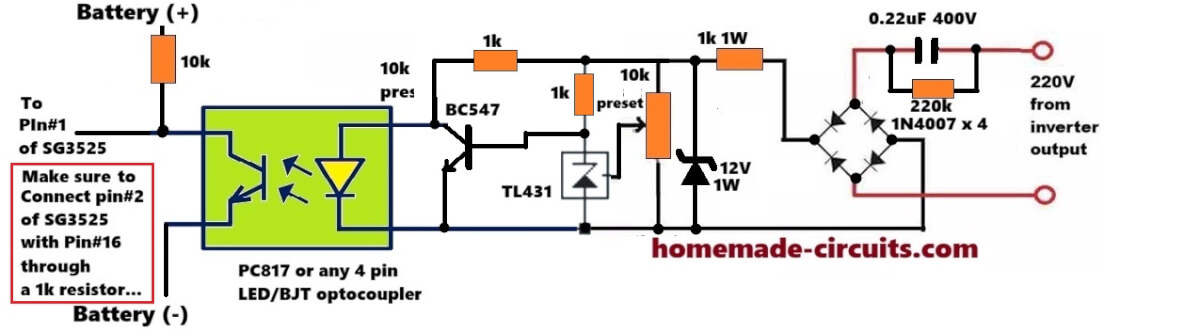
Hello I’m trying to build feedback for SG3525 with octocoupler and TL431 with variable resistor how do I connect this to my high voltage side there’s no auxiliary output just direct 300v
Using TL431, you can try this concept:
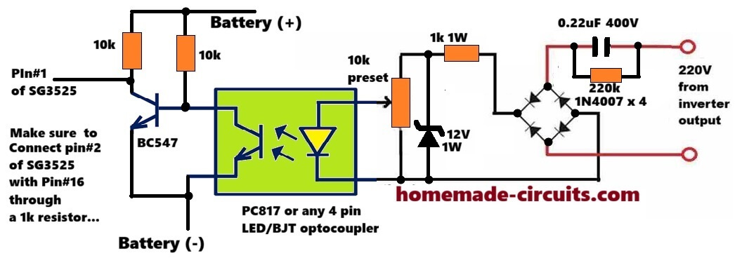
Hi, you can adopt this circuit for your application, however i did not use a TL431:
hi engineer
How can I learn electronics step by step on your site?
Hey Isa,
You can learn by asking me specific questions regarding the posted circuit ideas, on this website and I will try to answer them to you and help you to learn more…
sir how are you ineed temperature circuit diagram and humidity circuit
Abdul, you can get all the information on this page:
https://www.homemade-circuits.com/?s=temperature+humidity
Looking for a charge controller circuit for a wind turbine. Input 300Volts 7 amps output required is for two 300 amphr batteries connected in series.
Thanks I will try this out immediately
What is the battery voltage?
2 X 12 Lead acid batteries in series 24 volts for charging voltage should be around 32 volts
So you need a 300V to 32V DC to DC converter.
The power will be input 300 * 7= 2100 watts , and output current will be 2100 / 32 = around 60 amps.
For this you will need a buck converter circuit which you can easily design using the following calculator:
https://www.homemade-circuits.com/buck-converter-calculator/
Hi, I am looking for help with an automotive transmission controller. I would like to use a momentary button to control a contact/switch that would stay open when the button is pushed and stay closed when pushed again. The momentary button side would be 12v but the contact/trans controller side would be completely separate and see no power or ground. It functions based off of going from open to closed or closed to open. It can start off in the open position being off, close the circuit and it turns on, if not manually turned off by opening the circuit there is and auto off at low speed that occurs, this would leave the trans in off position with the circuit closed, you would then have to open the circuit to turn back on.
Hi, you can simply do it with 4017 IC circuit and an SSR. However the contact switch would need a separate power supply to operate…
Dear Swagatam,
I have been following your website as a hobbyist. i just want to make diy small washing machine about 3 to 4kg load with 12v or 230v ac. can you please advice me the motor and bi directional timer with pause
Thank you dear Prasad, I appreciate your interest very much.
It can be easily done using an IC 555 and IC 4017.
I will design it soon and let you know…
thank you Mr.swagatam. I will be happy to receive the same
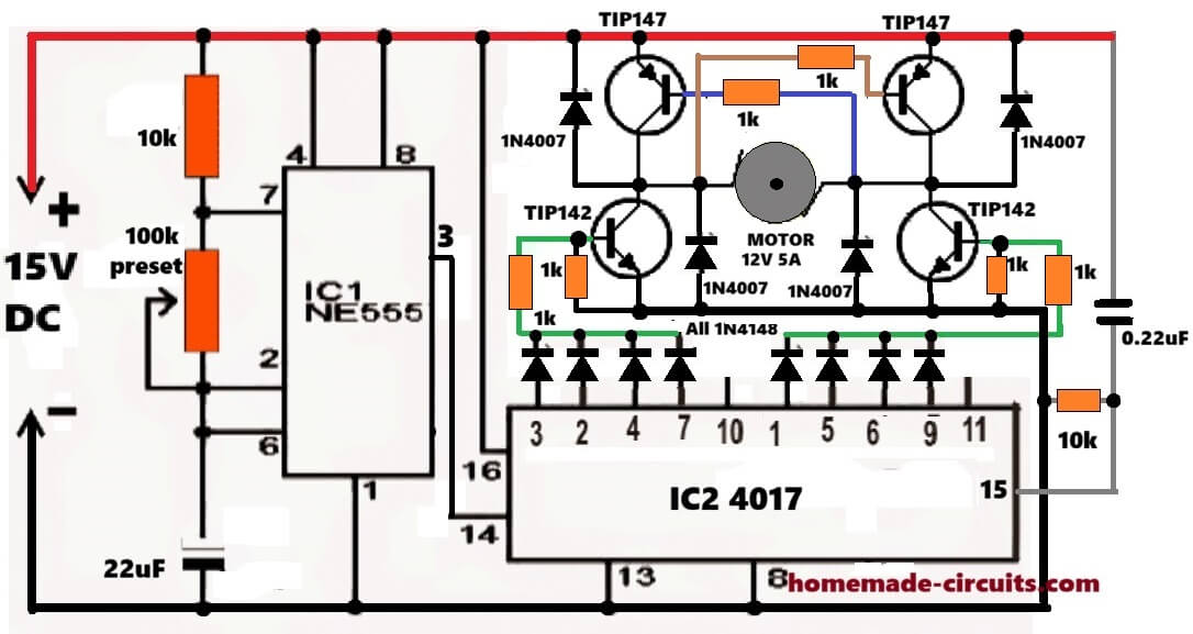
No problem Prasad, you can try the following circuit
can you please explain the diagram. And also substitute for transistors if any
Prasad, I have explained the full circuit in this post, please check it out:
https://www.homemade-circuits.com/make-this-simple-washing-machine/
Trying to use a LM2577-ADJ with 5v input from USB and to get 60v output.
I just cannot get any higher than 56.6v on my Fluke 77 multimeter, but my FNIRSI oscilloscope 1014D shows 59v. Not sure about that?
The R1/R2 ratio is set to R1=100k and R2=2.09k
Input cap = 100uF and output cap = 1000uF and inductor = 330uH
Schematic is based up https://www.ti.com/lit/ds/symlink/lm2577.pdf page 2. Tried different values for in and out elec caps, inductor and resistor ratio, and different diodes.
Any advice or have I just hit the limit on its output, with maybe an out-of-spec IC.
The output voltage you are seeing is quite normal for this configuration. Eventhough the resistor ratio correctly sets the output for 60V, yet boosting 5V up to 60V requires a very high duty cycle, close to the practical limit of the LM2577 IC.
Due to internal losses, switch saturation, diode drop, and efficiency limitations the IC typically cannot reach the exact theoretical value at such a high step-up ratio. So, an output around 56V to 58V is expected.
The difference between your multimeter and oscilloscope readings is also normal. The multimeter reads the average DC voltage while the oscilloscope displays peak voltage including ripple causing the higher reading on the scope.
Also if the circuit is powered from a USB source, then available input current may be limiting the output voltage further.
So in all your circuit appears to be functioning correctly and you are most likely observing the practical upper limit of the IC rather than a fault.
Many thanks Swagatam for a quick response.
I have come across similar problems with stated max values in datasheets, which is a bit misleading. This is something like 8% less than stated (theoretical value).
I will try a few changes to confirm practical limits.
1 – Revert back to the minimist component count and values.
2 – Check oscilloscope display settings for peak readings or whatever (V_pp, V_p, V_max, V_min,_avg, V_rms)
3 – Try using a more powerful 5v supply source.
Thank you Gray, for your understanding, sure, you can try those steps and let me know how it goes….please feel free too ask if you have any further doubts or questions..
Hi Swagatam – just an update
3 – tried using bench power supply for 5v supply with more Oomph, but that did not have any effect.
1&2 – In reverting back to original components. I removed 100uF across input, with just 0.2uF as smoothing on input. This had no effect.
This is where it gets interesting, as I removed all of the output smoothing capacitors (1000uF elec and 1uF ceramic).
In checking the output, I was somewhat surprised in getting the following waveform (sorry about file size) http://www.gb-online.co.uk/dump/LM2577-resized-20260504_103001.mp4
The Vpk is 95V dc coupled. The LM2577-ADJ was burning very hot, as it obviously did not like running above the 60v max with no output caps.
I should have put a 680uF across the output.
Got to wait for a replacement chip, and also change the 330uH for a 100uH
Hi Gray,
That waveform now explains the situation very clearly.
Once the output capacitors were removed, the boost converter output was no longer being filtered or averaged into a steady DC level. What you are now seeing on the oscilloscope are mainly the raw switching spikes and flyback energy pulses coming from the inductor, which is why the peak voltage is shooting up close to 95V.
Under this condition the LM2577 feedback loop also becomes unstable because it expects a reasonably smooth DC output for proper regulation. Without the output capacitor, the IC can momentarily overshoot far beyond the intended output voltage, causing excessive stress and heating of the internal switch transistor. So the overheating you observed is expected.
The output capacitor in a boost converter is actually a very critical part of the regulation system, not just a smoothing component. It stores the transferred energy between switching cycles and keeps the feedback loop stable.
A 680uF or 1000uF output capacitor should definitely be restored before further testing. Also, changing the inductor from 330uH to around 100uH may help improve the switching behavior for this application, especially at the high duty cycle required for stepping 5V up to 60V.
Hi Swagatam – We have reverted back to the Texas schematic with 100uH and output cap being 680uF but with the input cap only being 0.2uf (no elec cap).
Got the Vpk to be 59.5V and a ripple of about 600mV.
We did have to alter the R1 and R2 ratio as the resistors were way out of tolerance.
Going to next have a go at using LM358 + mosfet and multiple TIP32 for a 60V 30A power supply
So many thanks for listening to me.
Thank you Gray, for updating the results.
Sounds great! however LM358 + mosfet and multiple TIP32 looks like a linear regulator which will heat up a lot.
Instead why not design you own buck converter using the following tool:
https://www.homemade-circuits.com/buck-converter-calculator/
Is there a similar tool for Boost converter ?? Thanks
Yes, for boost converter you can try this tool:
https://www.homemade-circuits.com/ic-555-boost-converter-calculator/
Respected Sir,
I am interested in the circuit which track and remember the over and under voltage, the number of times it exceeds or goes low in 24 hours with memory.
I got totally confused with the products available on net/ amazon or other sites.
Please suggest something.
Mains over and under voltage tracking system
Hello Dhananjay, it is actually very easy.
You just need one LM393 IC and configure its one comparator to sense the high voltage, and configure the other comparator to sense the low voltage level.
Under both the conditions, the respective comparator outputs become high. These number of highs from the comparator outputs are fed to two separate digital counter circuits which display and record these ups and downs of the mains voltage.
You will need a battery backup for this circuit, to ensure the circuit memorizes the results even if the mains supply fails.
Respected Sir,
Thanks for your response and the valuable ideas.
Sir, since I don’t have sufficient time to get through the complex circuit and design the diagram, can you please share some assured readily available circuit boards in market.
Thank you Dhananjay, you can buy 4 separate modules, as given below.
1) 1no adjustable High voltage detector module.
2) 1no adjustable low voltage detector module.
3) 2nos digital counter circuits.
and now join these modules together as explained by me in the previous comment…
Hello Swag,
I kindly sent you a message on email and on facebook in case you didnt see it. But i think you blocked me, that is unfortunate. We genuinely needed your advice and help with our project.
I hope you understand that it is a legit request, and not spam.
Best
Rob (Bob Hein)
Hi Rob,
I never block any of my genuine readers.
I saw your email and have already replied to it.
Please check your email inbox…
All the best t you!