In this post we are going to understand this sensor called INA219, and this one is like a full smart sensor. It not only tells how much current is flowing but also tells voltage, and also calculates power, all in digital form. That means it talks with microcontroller through I2C lines. It is like an all-rounder current sensing chip.

INA219 Main Features and Specs
| Parameter | Description |
|---|---|
| Operating Voltage (VCC) | 3.0V to 5.5V (works fine with Arduino) |
| Bus Voltage Range | 0V to 26V |
| Shunt Voltage Range | ±40 mV (default, programmable) |
| Current Measurement | ±3.2 A (with 0.1Ω shunt) |
| Resolution | 0.1 mA to 0.8 mA depending on range |
| Power Calculation | Automatic (V × I) |
| Interface | I2C (2 wires only: SDA, SCL) |
| Address Configurable | Yes, up to 4 different addresses |
INA219 Internal Block Idea – How It Works Inside in Detail
Now let us try to go little deep and understand what this INA219 chip is actually doing inside, like step-by-step what is happening in the brain of this sensor. It is not a simple one like other current sensors. This one has lot of smart things built in. So let us break it down slowly.
It starts by checking the shunt resistor
So first of all, this sensor has a shunt resistor connected between its VIN+ and VIN- pins. This resistor is very small in value, mostly around 0.1 ohm or 0.01 ohm. This resistor is not inside the IC but already soldered on the small breakout board that we buy online.
Now when current flows through the load, then it also flows through this small resistor. That causes a very tiny voltage drop across the resistor, right?
So if 1 amp current flows and resistor is 0.1 ohm then voltage drop is 0.1V or 100 mV.
But INA219 does not take full 100 mV, it usually works with small input like ±40 mV maximum in default gain setting.
Then comes Differential Amplifier
Now inside the chip, there is one block called Differential Amplifier. This part is like a tiny smart op-amp. Its job is to measure only the voltage difference between VIN+ and VIN-. That means only the voltage drop across the shunt.
It ignores any voltage common to both sides (called common-mode voltage) and only amplifies the difference. This allows it to work even when the shunt is sitting on top of a high voltage line (up to 26V max).
Now this amplified signal goes to ADC (Analog to Digital Converter)
After the amplifier, this signal (the voltage across the shunt) is still analog, right?
So now comes the job of ADC. The INA219 has an inbuilt 12-bit ADC. That means it can divide the input voltage range into 4096 small parts.
This ADC converts the analog shunt voltage into digital number which the microcontroller can understand. So it takes this tiny voltage (maybe 25 mV, 30 mV, etc.) and gives out a number like 1350, 2250, etc. That number represents the current flowing.
At the same time, it also checks bus voltage
Now this is the smart part is, INA219 does not stop there. It also has a second ADC path inside which directly checks the bus voltage, means the voltage of the main line or the load which is connected across VIN+ and GND.
So for example if you are powering a motor with 12V then it will also measure that 12V automatically.
It does this using a separate measurement inside the chip, so now it has two values:
- The current (calculated from shunt voltage)
- The voltage (bus voltage)
Then it smartly calculates Power = Voltage × Current
Now the real smart thing happens here.
Inside the chip, the INA219 takes the bus voltage value and multiplies it with the current value (which it got from the shunt).
This gives the Power in Watts (actually in milliwatts).
So you do not need to do any external math in Arduino, like V × I = P. INA219 already does it and gives the value ready-made from inside its Power Register.
All values come out via I2C – no analog output needed
Once all this measuring and calculation is done inside the chip, then final values of current, voltage, and power are stored in internal registers.
You can read these values using the I2C bus. Just use the Wire library or any INA219 library in Arduino and it will talk to the chip through just two wires – SDA and SCL.
These are pure digital values. So you do not need to use any analog pins. No ADC conversion needed in Arduino. No noise problems. Everything is neat and ready.
INA219 IC Pinout
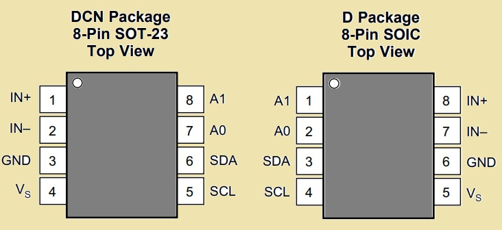

So VIN+ and VIN- are where we insert the load current. It measures current flowing from VIN+ to VIN- through shunt resistor.
How Current is Measured?
Inside the INA219 module, there is a shunt resistor, mostly it is 0.1 ohm or sometimes 0.01 ohm. So when current flows through that resistor, then a small voltage drop happens.
Example:
If 1 A current flows through 0.1 ohm:
Voltage = 1 × 0.1 = 0.1V = 100 mV
But INA219 measures only small drop like 40 mV max default. So that means max current = 40 mV / 0.1 ohm = 0.4 A. But if you configure gain setting, then it can go up to ±3.2 A.
INA219 Configured for Shunt and Bus Voltage Measurement

Power Supply and Load
At the very left side you see a power supply (can be a battery, adapter, solar panel, etc.). This is what powers your load, like a motor, bulb, or whatever.
This supply current has to pass through a shunt resistor, called R_SHUNT.
R_SHUNT (Current Sensing Resistor)
This is a very low value resistor, like 0.1 ohm or 0.01 ohm. When current flows through this resistor, then a small voltage drop appears across it.
This drop is called:
V_SHUNT = V_IN+ - V_IN-Normally this is just a few millivolts – maybe 50mV max.
So basically INA219 looks at this voltage drop and from this, it calculates current using Ohm’s law:
I = V_SHUNT / R_SHUNTBus Voltage Line (V_BUS)
At the bottom, there is another voltage – this is the bus voltage or the actual voltage across your load (battery, etc).
V_BUS = V_IN- – GNDIt can be from 0V to 26V. Most of the time, it is 12V, 24V, etc.
So this chip can read both the current (using the shunt) and the voltage (bus line) at same time!
INA219 With Input Filtering

This diagram is showing how to connect a filter before the INA219 inputs so that any noise or AC ripple is removed from the current sensing signal. Let us understand how and why each part is used.
Left Side: Shunt Resistor and Input Filter
R_SHUNT
Like before, this is the main current sensing resistor. It sits in series with the load so all current flows through it.
So this creates a small voltage drop across it:
V_SHUNT = V_IN+ – V_IN-Problem: High-Frequency Noise
In some circuits, especially switching circuits (like motors, inverters, solar MPPT), there will be AC noise or spikes on the supply line.
If this noise reaches INA219, then it can mess up the current reading badly.
So we must filter that noise.
Solution: RC Low-Pass Filter
To remove noise, we add a simple RC low pass filter at the input side:
R_FILTER (10 ohms each)
These resistors are added in series with V_IN+ and V_IN- going into the INA219.
Their job is to limit the current going into the IC and work with the capacitor to filter noise.
We use one resistor on each line – so two 10Ω resistors.
Capacitor (0.1µF to 1µF Ceramic)
This capacitor is placed between the two input lines (V_IN+ and V_IN-), right after the resistors.
So it sits across the shunt voltage signal.
It works like a short circuit for high frequency noise but passes low-frequency DC signal (the real shunt voltage) cleanly.
RC Filter Cut-off Frequency
This filter has a cut-off frequency (f_c) that decides how much noise it can kill.
Formula:
f_c = 1 / (2π * R_FILTER * C)Suppose:
- R_FILTER = 10Ω
- C = 0.1µF
Then:
f_c = 1 / (2 * 3.14 * 10 * 0.1e-6)
= 159,000 Hz (≈ 159 kHz)
So this filter kills anything above 159kHz which is perfect for removing switching noise (PWM, SMPS, etc).
If we use 1µF cap then f_c becomes 15.9kHz, even better for low-frequency filtering.
Inside the INA219 Block
VIN+ and VIN- Pins
After filtering, the clean signal enters the INA219 at these two pins.
PGA (Programmable Gain Amplifier)
This amplifies the tiny voltage across the shunt.
ADC
Then this amplified signal is converted to digital form.
Registers:
- Voltage Register – stores bus voltage
- Current Register – stores measured current
- Power Register – stores voltage × current = power
I2C Interface
All data is sent to your microcontroller using just 2 wires:
- SDA (Data)
- SCL (Clock)
Pull-up resistors shown for 3.3V I2C system.
A0 and A1
Used for I2C address selection in case you're using more than one INA219 on the same bus.
Power Supply
- V_S is the chip's power pin.
- Give it 3.3V or 5V as per your microcontroller.
- GND should be common with your MCU.
To Summarize:
We take shunt voltage. Then we pass it through 10Ω resistors + small ceramic cap to kill noise. Then INA219 gets a clean DC signal.
Now it starts to measures current, voltage, and power. Then sends data to Arduino or ESP using I2C.
No analog pin needed.
Filter is super important if you are using this in any system where noise or spikes are possible (solar charger, motor driver, inverter, buck converter, etc).
Typical INA219 Module Pinout (with Arduino)
| INA219 Pin | Connects To |
|---|---|
| VCC | +5V or 3.3V from Arduino |
| GND | Arduino GND |
| SDA | A4 (on Uno) |
| SCL | A5 (on Uno) |
| VIN+ | From Load Positive |
| VIN- | To Load Negative |

Arduino Code Example (Using Adafruit INA219 Library)
#include <Wire.h>
#include <Adafruit_INA219.h>

Adafruit_INA219 ina219;

void setup() {
  Serial.begin(9600);
  ina219.begin(); // Start sensor
}

void loop() {
  float shuntVoltage = ina219.getShuntVoltage_mV();
  float busVoltage = ina219.getBusVoltage_V();
  float current = ina219.getCurrent_mA();
  float power = ina219.getPower_mW();

  Serial.print("Bus Voltage: "); Serial.print(busVoltage); Serial.println(" V");
  Serial.print("Shunt Voltage: "); Serial.print(shuntVoltage); Serial.println(" mV");
  Serial.print("Current: "); Serial.print(current); Serial.println(" mA");
  Serial.print("Power: "); Serial.print(power); Serial.println(" mW");
  Serial.println("----------");
  delay(1000);
}
How to Connect Load?
You can connect the load in the following manner:
Source + ----> VIN+ INA219 VIN- ----> Load + ----> Load - ----> Source -So we put the sensor in series with load's positive side. The current goes through VIN+ to VIN-, then passes through shunt resistor, and then INA219 calculates current.
Registers and Internal Working
If you want to go deep, then INA219 uses following internal registers:
| Register | Function |
|---|---|
| Configuration | Gain, ADC mode, etc. |
| Shunt Voltage | Raw measured across shunt |
| Bus Voltage | Main line voltage |
| Power | Result of V × I |
| Current | Shunt voltage ÷ shunt R |
| Calibration | You set this for scaling |
If you are not using library then you can use I2C commands to write and read from these registers manually.
How to connect Arduino with computer
This part is very simple. Just do the following:
- Use a USB cable (Type-A to B or Micro-USB depending on your Arduino model)
- Plug one end into your computer
- Plug the other end into the Arduino board
Now when you open the Arduino IDE click on:
Tools→Port→ Select the COM port (like COM3, COM5, etc.)Tools→Board→ Select your board (e.g., Arduino Uno)
Then click on the Serial Monitor to view the data being printed from your code.
That's it, now your PC is connected to Arduino and you can see power readings live.
just remember these things:
- Serial Monitor must be set to 9600 baud (match this with
Serial.begin(9600);) - You can open Serial Monitor from Arduino IDE menu:
Tools→Serial Monitoror pressCtrl + Shift + M - Make sure only one program is using the COM port at a time (Serial Monitor or Serial Plotter — not both)
How to Activate a Relay when Power Exceeds a Threshold
To do this we just:
Pick a digital pin, say D8, then connect a 5V relay module (or transistor driver if using raw relay).
Then add a condition in the Arduino code to activate the relay when power is higher than your desired limit
Let us say your threshold is 5000 mW (5 watts). Then we can use the following code and circuit diagram:
Arduino Code for Overload Cut-OFF
#include <Wire.h>
#include <Adafruit_INA219.h>

Adafruit_INA219 ina219;

const int relayPin = 8; // Relay connected to D8
const float powerThreshold = 5000.0; // 5000 mW = 5 watts

void setup() {
  Serial.begin(9600);
  ina219.begin(); // Start sensor
  pinMode(relayPin, OUTPUT);
  digitalWrite(relayPin, LOW); // Keep relay off initially
}

void loop() {
  float shuntVoltage = ina219.getShuntVoltage_mV();
  float busVoltage = ina219.getBusVoltage_V();
  float current = ina219.getCurrent_mA();
  float power = ina219.getPower_mW();

  Serial.print("Bus Voltage: "); Serial.print(busVoltage); Serial.println(" V");
  Serial.print("Shunt Voltage: "); Serial.print(shuntVoltage); Serial.println(" mV");
  Serial.print("Current: "); Serial.print(current); Serial.println(" mA");
  Serial.print("Power: "); Serial.print(power); Serial.println(" mW");
  Serial.println("----------");

  // Relay control logic
  if (power > powerThreshold) {
    digitalWrite(relayPin, HIGH); // Turn ON relay
  } else {
    digitalWrite(relayPin, LOW);  // Turn OFF relay
  }

  delay(1000);
}
Relay Control Circuit Diagram

Relay module wiring
If you are using a ready-made 5V relay module then connect:
- Relay VCC to Arduino 5V.
- Relay GND to Arduino GND.
- Relay IN to Arduino D8.
If you are using a bare relay then you will need:
- NPN transistor (like BC547 or 2N2222).
- 10k resistor to transistor base.
- Flyback diode (1N4007) across relay coil.
Few Important Things to Always Remember – Safety + Tricks for INA219
Never Apply More Than 26V on Bus Voltage (VIN+)
OK see, this INA219 can measure voltage only up to 26V DC on its VIN+ input (this is the voltage of your load or battery or whatever you're checking).
If you give more than 26V, like maybe 30V or 40V then the IC will burn or break internally. No internal protection is there for overvoltage.
So always check your input voltage first. If you are using 24V battery, then it is fine. If 12V load then also fine. But if 36V solar panel or higher, then do not use directly.
You can add voltage divider before VIN+ if needed or better use INA260 for high voltage systems.
This Sensor is Not Isolated – Never Connect to High Voltage AC
This is very important for safety.
INA219 is not an isolated sensor, that means the VIN+ and VIN– pins are directly connected to the system ground through shunt resistor.
So if you try to put this directly in AC mains line like 220V or 110V AC, without isolation – your Arduino or ESP will get full voltage and you may get electric shock or blow up everything.
So only use this INA219 for DC systems like:
- Battery charging
- Solar panel
- DC motor
- LED driver
If you want to measure AC mains current or voltage, then use an isolated sensor like a CT sensor (current transformer) or Hall effect sensor like ACS37800 or similar.
For Bidirectional Current – Set Offset and Gain Properly
OK now sometimes in your circuit the current can flow forward and backward. For example:
- Charging and discharging battery
- Power flowing to and from inverter
- Regenerative braking in motor
In such case, you need bidirectional current sensing. INA219 supports this. But we must set the gain and offset in software properly.
Normally it gives 0A at mid-voltage (around 2048 in 12-bit) and goes up or down based on direction.
So if you are seeing weird negative values or too high values, then just check your gain, offset and calibration settings.
Also make sure the shunt resistor is correct value and connection polarity is not reversed.
Do Not Short VIN+ and VIN– Without Load
Another hidden problem, sometimes people connect both VIN+ and VIN– directly together without any actual load or resistor in between.
That creates a zero voltage difference but because of small noise or internal offset, INA219 will still try to measure something and give random small values.
Also if wires are long then it may show false current even if nothing is flowing.
So always make sure your VIN+ and VIN– are connected across a real load (like LED, battery, motor, etc.), or at least through a proper shunt resistor.
You Can Change I2C Address with A0 and A1 Pins
Now this is useful trick – if you want to use more than one INA219 sensor in same project (like for multiple batteries or multiple motors) then you need to change their I2C addresses.
By default INA219 has fixed I2C address. But it gives two pins: A0 and A1.
If you short these pins to GND or VCC then you can get up to 4 different addresses like:
| A1 | A0 | I2C Address |
|---|---|---|
| 0 | 0 | 0x40 |
| 0 | 1 | 0x41 |
| 1 | 0 | 0x44 |
| 1 | 1 | 0x45 |
So just solder jumpers or connect with jumper wires and your I2C scanner will detect new address.
Then you can talk to multiple INA219 chips using same two I2C wires. No extra pin needed. Very smart, right!
So bottom line is, INA219 is powerful but not foolproof. If we follow the above 5 points carefully then it will work for years and give clean accurate readings.
Always double-check:
- Voltage not more than 26V
- No AC mains connection
- Shunt and load properly connected
- I2C address configured if using many
Why We Use INA219?
now let us really understand why this INA219 sensor is so useful and why we prefer it in our projects instead of other current sensors like ACS712 or shunt+opamp combo.
This tiny chip is like a combo pack, it gives us many features in just one IC. Let us look at all the benefits one by one, slowly:
It is Fully Digital – No Analog Pin, No Analog Reading Needed
Now the first big reason is – this sensor gives you digital output only through I2C protocol. That means no need to use Arduino analog pins and no need to read noisy analog signals or do extra maths.
Everything, current, voltage, power is calculated inside the chip and given as clean digital data. So Arduino or ESP reads it just like reading a temperature or time.
No confusion, no analog errors, no capacitor filtering, nothing. Just 2 wires (SDA and SCL), and you are done.
It Measures Current, Voltage, and Power – All 3 in One IC
Now this is super helpful. Normally, to measure current and voltage, we need two sensors or two separate setups.
But INA219 gives you all 3 important things:
- Current through the shunt
- Bus voltage (load voltage)
- Power by multiplying voltage × current
So it becomes a complete power monitoring tool.
You do not have to do extra calculation. The IC itself gives you power in milliwatts. So we can use it in battery charging, solar monitoring, motor current limiters – anywhere we need full power tracking.
Only 2 Wires for Communication – I2C Makes It Super Simple
The INA219 works on the I2C protocol which means we need only 2 wires:
- SDA – for data
- SCL – for clock
That is it. No analog wires, no complex setup.
You can connect multiple I2C devices on same two wires also, by changing address. So if you have a display, a sensor, and INA219 – all can go on same I2C line. Just connect the pull-up resistors and everything works.
This is very useful especially for ESP32 or Arduino Nano, which have less number of pins.
It Is Much More Accurate Than ACS712
Now if you compare with old-school current sensor like ACS712, you will see big difference.
ACS712 gives analog output and it is very noisy. You need to average it, filter it and still there will be error of 100 mA or more.
Also the zero current level drifts with temperature in ACS712. But INA219 gives stable and accurate digital output and resolution is in microamps.
So if you want precise reading (for example for battery management or solar panel tracking) then INA219 is much better choice. It can even measure small standby currents or low load currents, where ACS712 will just show garbage.
Works with 3.3V Also – Good for ESP8266, ESP32, STM Boards
One more reason, this chip works perfectly on 3.3V systems. So if you are using ESP8266, ESP32, or STM32 board which do not use 5V, then no problem.
INA219 will work fine even with 3.3V I2C logic and power. Just power it with 3.3V and it will still measure voltages up to 26V on the bus side.
This makes it flexible for modern low-voltage boards also.
So Finally Why We Pick INA219 Again and Again
To put it straight – we use INA219 because it is fully digital, super accurate and gives all 3 values in one sensor. No analog mess, no maths in code, no temperature drift, no pin headache.
Just connect 2 wires, call a library and read the values in milliamp, millivolt, and milliwatt.
This IC is perfect for:
- Battery charging projects
- Power consumption monitoring
- Solar energy tracking
- Load protection and current limit alerts
- Motor power monitoring
It is like plug-and-play power meter for Arduino and ESP.
Ready-Made INA219 Module Overview
Usually you will get the INA219 in a blue breakout board with 6 pins (VCC, GND, SDA, SCL, VIN+, VIN-) and a 0.1 ohm shunt resistor already soldered. Just connect it directly with your microcontroller and you are ready to go.

Need Help? Please Leave a Comment! We value your input—Kindly keep it relevant to the above topic!