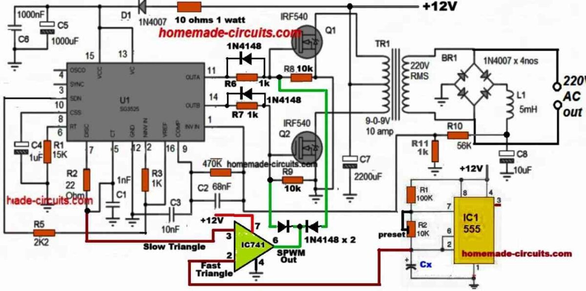
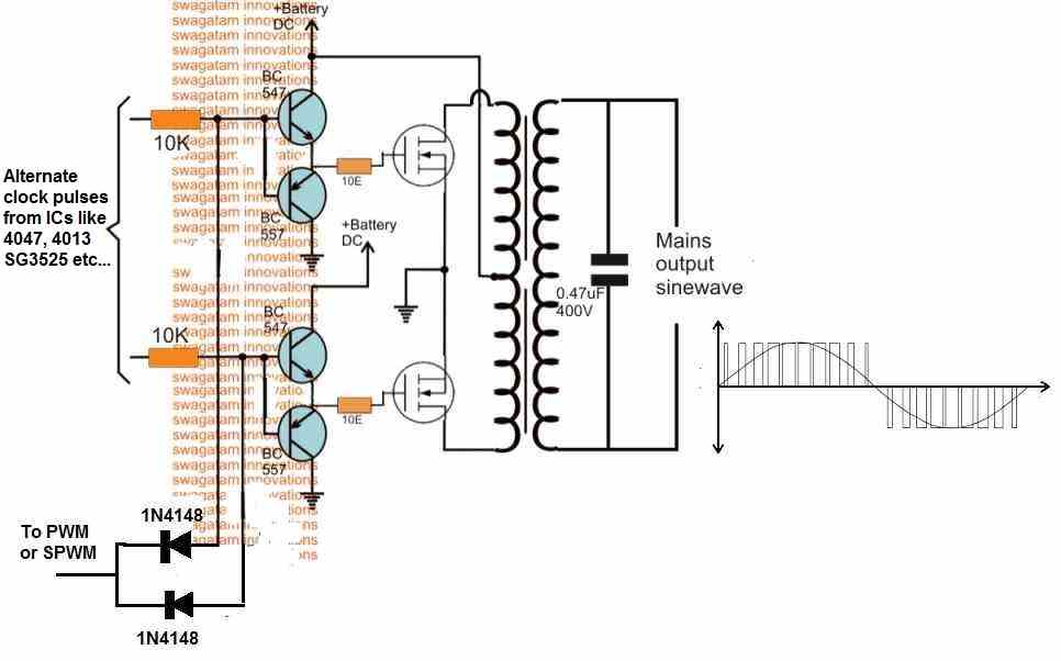
In this post we will discuss two methods of designing pure sine wave inverter circuits using 555 IC based SPWM processing. In the first concept we connect the 555 processors directly with the SG3525 outputs and do the sine wave conversion directly at the MOSFET gates. In the second concept we do it externally and […]
Inverter Circuits
Pseudo-sinusoidal IC 4047 Inverter Circuit
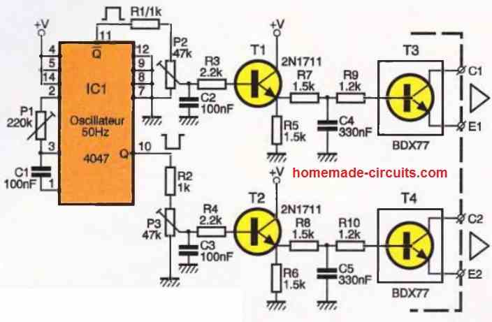
From a continuous source, battery, or vehicle alternator, it is possible to produce a 50 Hz voltage/pseudo-sinusoidal waveform, using this simple IC 4047 inverter circuit. The design is capable of operating many low-power devices that require a voltage of 220 V AC, typically supplied by the AC mains grid distribution network. The power of this […]
Design your own Sine Wave Inverter Circuit from the Scratch [Tutorial]
In this article I have explained comprehensively regarding how to design a sine wave inverter without any form of coding or complex circuit designs. The included designs are simple yet extremely precise with their sine waveform structure. You might have often felt discouraged, thinking that making a sine wave inverter from the scratch can be […]
IC IR2111 H-Bridge Inverter Circuit with Shut Down

This circuit is basically a H bridge inverter where two IC IR2111 are working for driving four MOSFETs that are connected in H bridge way. We also see that there is a overload and over current shut down using BC547 small transistors. So what happens is that we can run a load with AC waveform […]
Modified Inverter Circuits using 4049, 4093 ICs

The following inverter designs are unique modified sine wave inverter concepts designed me. The entire unit along with the oscillator stage and the output stage can be easily built by any electronic enthusiast at home. The present designed will be easily able to support 500 VA of output load. Let’s try to understand the circuit […]
Adjustable RMS Modified Inverter Circuit using BJTs

A very interesting circuit of a RMS controlled modified sine wave inverter is discussed in this article which incorporates just ordinary transistors for the proposed implementations. The use of transistors typically makes the circuit easier to understand and more friendly with the new electronic enthusiasts. The inclusion of a PWM control in the circuit makes […]