• Skip to main content
  • Skip to primary sidebar

Homemade Circuit Projects

Need circuit help? Post them in the comments! I've answered over 50,000!

Blog | Categories | About | Contact | Calculators-online
You are here: Home / Lamps and Lights / Beacon Level Indicator Circuit for Combine Harvester Grain Tanks

Beacon Level Indicator Circuit for Combine Harvester Grain Tanks

Last Updated on July 6, 2019 by Swagatam 2 Comments

In this post I have explained a beacon indicator circuit for combine harvester grain tanks. The idea was requested by Mr. John Bosch.

Table of Contents
  • The Design
  • How it Works

warning message: electricity is dangerous, proceed with caution
47751fl

Circuit Objectives and Requirements

  1. I would like to retrofit the rotating beacon grain tank level indicator system shown below,  to my older combine harvester.
  2. The particular part of the system I want to build is this:
  3. Turns on automatically when the grain tank level reaches three-quarter.
  4. Beacon lights begin an alternating pattern once the three-quarters full sensor is triggered; beacon lights remain on for 10 seconds then turn off for 10 second continually repeating until the grain tank full sensor is triggered.
  5. Once the grain tank full sensor is triggered the beacon lights remain on constantly.
  6. Would you be able to design a circuit to perform this function? I already have the bin level sensor, and it is a normally open type of contact.
  7. The specs on the sensor are: 48V, .5amp, 10 watt, 300mA, so even though I’m planning on using LED beacon lights, I suspect the output of any circuit would have to trigger a relay to a power circuit for the beacons. I would also like to be able to switch the system off from the control station of the combine.
  8. Thanks in advance for any and all input!

The Design

The proposed beacon level indicator for grain tanks can be very simply implemented using an IC 555 circuit in its astable mode, as shown below:


Beacon Level Indicator Circuit for Combine Harvester Grain Tanks

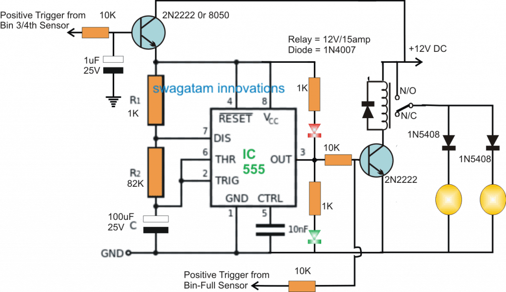
The IC 555 is configured in its standard astable mode (flashing mode), where R1,R2, and C values determine the flashing rate of the IC at its pin#3.

These values are calculated to produce a reasonably precise 5 second ON/OFF switching on pin#3 of the IC.

How it Works

Pin#3 can be seen connected with a relay driver stage whose contacts are configured with the indicator beacon LED lamps.

When the +12V supply from the relay side is switched ON, the circuit is put on a standby position and ready to respond to the signals from the bin sensors.

As soon as the first signal is received from the "3/4 tank full sensor" the astable gets powered through the relevant 2N2222 transistor on the top left, and the circuit immediately begins oscillating at the set rate.

The relay follows the ON/OFF triggers from pin#3 of the IC and initiates the required 5 second ON/OFF activation for the attached rotating beacon lights, indicating that the 3/4 tank full level is reached.

The above ON/OFF is sustained for a period of time until the grain tank reaches its full level, when the subsequent trigger from the "full level sensor" causes a permanent activation of the driver transistor and the relay.

The relay now becomes locked and enables both the beacon indicator lamps to be ON and rotating, indicating the "tank full" situation to the user.

You'll also like:

  • 1.  Arduino RGB Flowing Sequential Light Circuit
  • 2.  Rotating LED Chakra Circuit for God Idols
  • 3.  Make this 2 Pin Bi-Color LED Flasher Circuit
  • 4.  Simple LED Tubelight Circuit
  • 5.  Rechargeable LED Lantern Circuit Using Dynamo
  • 6.  Battery Over Charge Protected Emergency Lamp Circuit

About Swagatam

I am an electronics engineer with over 15 years of hands-on experience. I am passionate about inventing, designing electronic circuits and PCBs, and helping hobbyists bring their projects to life. That is why I founded homemade-circuits.com, a website where I share innovative circuit ideas and tutorials. Have a circuit related question? Leave a comment.... I guarantee a reply!

Previous Post: « Corona Effect Generator Circuit
Next Post: Arduino Digital Clock Using RTC Module »

Reader Interactions

Comments

  1. John Bosch says

    February 5, 2017 at 3:22 pm

    Hi Swag! It soon will be spring and I'm getting ready to build this circuit. One question: what are the red and green items that look like diodes in the diagram above, and what model are they?
    Thanks
    John

    Reply
    • Swagatam says

      February 6, 2017 at 4:07 am

      Wish you all the best John, the read/green parts are the LED indicators

      Reply

Need Help? Please Leave a Comment! We value your input—Kindly keep it relevant to the above topic! Cancel reply

Your email address will not be published. Required fields are marked *

Primary Sidebar


Subscribe to New Circuits

Categories

  • Arduino Projects (87)
  • Audio and Amplifier Projects (132)
  • Automation Projects (17)
  • Automobile Electronics (101)
  • Battery Charger Circuits (83)
  • Datasheets and Components (104)
  • Electronics Theory (143)
  • Free Energy (37)
  • Games and Sports Projects (11)
  • Grid and 3-Phase (19)
  • Health related Projects (25)
  • Home Electrical Circuits (12)
  • Indicator Circuits (14)
  • Inverter Circuits (87)
  • Lamps and Lights (142)
  • Meters and Testers (69)
  • Mini Projects (46)
  • Motor Controller (64)
  • Oscillator Circuits (27)
  • Pets and Pests (15)
  • Power Supply Circuits (108)
  • Remote Control Circuits (50)
  • Security and Alarm (64)
  • Sensors and Detectors (101)
  • Solar Controller Circuits (59)
  • Temperature Controllers (42)
  • Timer and Delay Relay (49)
  • Transmitter Circuits (29)
  • Voltage Control and Protection (37)
  • Water Controller (36)


  • Privacy Policy
  • Cookie Policy
  • Disclaimer
  • Copyright
  • Videos
  • Sitemap


People also Search

555 Circuits | 741 Circuits | LM324 Circuits | LM338 Circuits | 4017 Circuits | Ultrasonic Projects | SMPS Projects | Christmas Projects | MOSFETs | Radio Circuits | Laser Circuits | PIR Projects |

Social Profiles

  • Twitter
  • YouTube
  • Instagram
  • Pinterest
  • My Facebook-Page
  • Quora
  • Stack Exchange
  • Linkedin


  • © 2025 · Swagatam Innovations