• Skip to main content
  • Skip to primary sidebar

Homemade Circuit Projects

Need circuit help? Post them in the comments! I've answered over 50,000!

Blog | Categories | About | Hire Me | Contact | Calculators-online
You are here: Home / Oscillator Circuits / Build this Simple Zener-Stabilized Wien Bridge Sine Wave Generator Circuit

Build this Simple Zener-Stabilized Wien Bridge Sine Wave Generator Circuit

Last Updated on July 21, 2026 by Swagatam Leave a Comment

This zener diode stabilized Wien Bridge sine wave oscillator circuit is very easy to build and test, let me explain full working in simple way. Basically here we are using TL072 opamp which needs dual supply like +15V on pin 8 and -15V on pin 4. Pin 1 is our main output pin from where sine wave will come out.

Table of Contents
  • Positive Feedback Loop (Frequency Selection)
  • Negative Feedback Loop (Gain Control Setup)
  • Startup & Amplitude Stabilization Mechanism
    • Tuning & Final Output
    • Biggest Advantage
    • Sources

Positive Feedback Loop (Frequency Selection)

First look at positive feedback side connected to non-inverting input pin 3. Here Rs and Cs are connected in series from output pin 1 to pin 3. Also Rp and Cp are connected in parallel from pin 3 to ground. This network is called Wien bridge filter network. This part decides what frequency sine wave will generate.
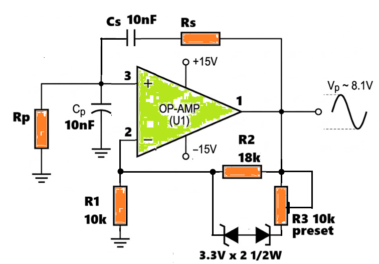
For 1 kHz: Use Rs = Rp = 15.9 kOhm (standard 16 kOhm).
For 10 kHz: Use Rs = Rp = 1.59 kOhm (standard 1.6 kOhm).

Formula is simple:

Frequency = 1 / (2 * 3.1416 * R * C)

When you put Cs and Cp as 10 nF (0.00000001 F) and set Rs and Rp to 16000 ohms (16k), then:

Frequency = 1 / (2 * 3.1416 * 16000 * 0.00000001) = 994.7 Hz (approx 1 kHz)

If you change Rs and Rp to 1600 ohms (1.6k) using a switch, then:

Frequency = 1 / (2 * 3.1416 * 1600 * 0.00000001) = 9947 Hz (approx 10 kHz)

Negative Feedback Loop (Gain Control Setup)

Now look at negative feedback side connected to inverting input pin 2. This part controls the gain so sine wave stays stable and does not get distorted into square wave. R1 10000 ohm (10k) resistor is connected from pin 2 to ground. R2 22000 ohm (22k) resistor is connected between output pin 1 and pin 2.

In parallel with R2, we have added two 3.3V zener diodes connected back to back along with one 10000 ohm (10k) preset R3 in series.

Formula for initial opamp gain:

  • Gain = 1 + (R2 / R1)
  • Gain = 1 + (22000 / 10000) = 3.2

Startup & Amplitude Stabilization Mechanism

When you turn on power supply first time, then voltage is very small. At this low voltage, zener diodes will not conduct at all and act like open switch. So only R2 is active, and because the gain is 3.2 (which is greater than 3), oscillation starts automatically without any delay.

Once oscillation starts, sine wave voltage starts growing big on output pin 1. When output voltage reaches around 3.9V peak (3.3V zener voltage + 0.6V diode forward voltage), these two 3.3V zener diodes turn ON and start conducting current.

When zeners turn ON, they bring preset R3 into parallel with R2.

Total Feedback Resistance = (R2 * R3) / (R2 + R3)

Because two resistors in parallel means total feedback resistance drops down, the effective gain formula changes:

Stabilized Gain = 1 + (Total Feedback Resistance / R1)

When feedback resistance drops down, opamp gain automatically drops down to exactly 3. Because gain becomes exactly 3, the sine wave amplitude gets fixed and stops growing further.

Tuning & Final Output

By adjusting that 10000 ohm (10k) preset R3, you can fine tune the signal:

  • If sine wave is looking flat or clipped at top, turn preset to increase resistance.
  • If oscillation stops, reduce preset slightly.

Like this you get super stable and smooth sine wave output around 8.1V peak to peak. Full simple bro, no complicated funda here.

Biggest Advantage

The biggest advantage of your Zener Wien bridge design is extreme simplicity and instant, reliable oscillation without needing complex control loops. It’s the ultimate design for quick lab signal generators, microcontroller clock sources, or audio test tones where absolute pure 0.1% THD isn't strictly required.

Simulation Text for Falstad Simulator:
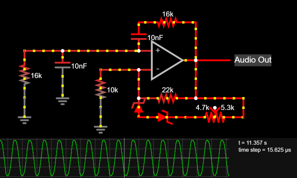
wien bridge simulation textDownload
zener stabilized wien bridge sine oscillator simulation results

Sources

  • electronics.stackexchange.com
  • en.wikipedia.org

You'll also like:

  • 4011 pinout truth table compressedCMOS Astable, Bistable, Monostable Circuits Explained
  • cricket sound simulatorElectronic Cricket Sound Generator Circuit
  • Understanding CMOS IC 4035 Datasheet – 4-Bit Parallel In Parallel Out Shift Register
  • 3phasegeneartorUsingTransistorsTransistor based 3 Phase Sine Wave Generator Circuit

Filed Under: Oscillator Circuits Tagged With: Bridge, Build, Simple, Stabilized, Wien, Zener

About Swagatam

I am an electronics engineer and doing practical hands-on work from more than 15 years now. Building real circuits, testing them and also making PCB layouts by myself. I really love doing all these things like inventing something new, designing electronics and also helping other people like hobby guys who want to make their own cool circuits at home.

And that is the main reason why I started this website homemade-circuits.com, to share different types of circuit ideas..

If you are having any kind of doubt or question related to circuits then just write down your question in the comment box below, I am like always checking, so I guarantee I will reply you for sure!


Previous Post: « SMPS LED Bulb Circuit with Dimmer Control using IC IRS2530D

Reader Interactions

Need Help? Please Leave a Comment! We value your input—Kindly keep it relevant to the above topic! Cancel reply

Your email address will not be published. Required fields are marked *

Primary Sidebar


Categories

  • Arduino Projects (95)
  • Audio and Amplifier Projects (134)
  • Automation Projects (18)
  • Automobile Electronics (103)
  • Battery Charger Circuits (88)
  • Datasheets and Components (109)
  • Electronics Theory (150)
  • Energy from Magnets and Earth (40)
  • Games and Sports Projects (11)
  • Grid and 3-Phase (20)
  • Health related Projects (27)
  • Home Electrical Circuits (13)
  • Indicator Circuits (16)
  • Inverter Circuits (100)
  • Lamps and Lights (163)
  • Meters and Testers (72)
  • Mini Projects (28)
  • Motor Controller (68)
  • Oscillator Circuits (29)
  • Pets and Pests (15)
  • Power Supply Circuits (91)
  • Remote Control Circuits (50)
  • Security and Alarm (65)
  • Sensors and Detectors (107)
  • SMPS and Converters (46)
  • Solar Controller Circuits (61)
  • Temperature Controllers (43)
  • Timer and Delay Relay (50)
  • Voltage Control and Protection (44)
  • Water Controller (37)
  • Wireless Circuits (31)


Circuit Simulator

circuit simulator image


Subscribe to get New Circuits in your Email


Other Links

  • Privacy Policy
  • Cookie Policy
  • Disclaimer
  • Copyright
  • Videos
  • Sitemap

People also Search

555 Circuits | 741 Circuits | LM324 Circuits | LM338 Circuits | 4017 Circuits | Ultrasonic Projects | SMPS Projects | Christmas Projects | MOSFETs | Radio Circuits | Laser Circuits | PIR Projects |


Recent Comments

  • Swagatam on Phase Shift Oscillator Circuits – Wien-Bridge, Buffered, Quadrature, Bubba
  • Swagatam on PWM Inverter Using IC TL494 Circuit
  • Swagatam on Bicycle Generator Circuit
  • Swagatam on Digital Capacitance Meter Circuit Using Arduino
  • Swagatam on 7 Easy Voltage Doubler Circuits Discussed

Social Profiles

  • Twitter
  • YouTube
  • Instagram
  • Pinterest
  • My Facebook-Page
  • Stack Exchange
  • Linkedin

© 2026 · Swagatam Innovations