The IRFP460 MOSFET is an N-channel MOSFET. It is rated for a drain-source breakdown voltage of 500V and a continuous drain current of 20A. This MOSFET is a third-generation device designed with fast switching and low on-resistance in mind. Specifically, it has a maximum drain-source on-state resistance of 0.27 Ohms.
Basically this IRFP460 MOSFET is suitable for switching applications at high voltages making it ideal for use in switch mode power supplies, DC-to-DC converters, motor drivers, inverters, and other power conversion applications.
It can handle up to 80A pulses and can dissipate 280W of power if adequate cooling is provided.
IRFP460 MOSFET Main Characteristics
- Type: N-Channel
- Maximum Drain to Source Voltage: 500 Volts
- Maximum Drain to Source Current: 20 Amps
- Minimum Drain to Source Resistance = 0.27 Ohms
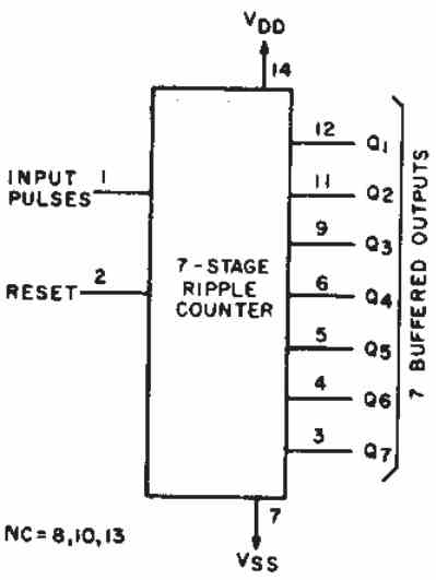
Pinout Details

Absolute Maximum Ratings
| Parameter | Description | Value | Unit |
|---|---|---|---|
| I_D @ T_C = 25°C | Continuous Drain Current at 25°C | 20 | A |
| I_D @ T_C = 100°C | Continuous Drain Current at 100°C | 13 | A |
| I_DM | Pulsed Drain Current (short bursts) | 80 | A |
| P_D @ T_C = 25°C | Maximum Power Dissipation | 280 | W |
| Linear Derating Factor | Power dissipation reduction per °C above 25°C | 2.2 | W/°C |
| V_GS | Maximum Gate-to-Source Voltage | ±20 | V |
| E_AS | Single Pulse Avalanche Energy | 960 | mJ |
| I_AR | Avalanche Current (short duration) | 20 | A |
| E_AR | Repetitive Avalanche Energy | 28 | mJ |
| dv/dt | Peak Diode Recovery Rate | 3.5 | V/ns |
| T_J, T_STG | Operating & Storage Temperature Range | -55 to 150 | °C |
| Soldering Temperature | Max soldering temperature (for 10s, 1.6mm from case) | 300 | °C |
| Mounting Torque | Recommended screw torque for mounting | 10 (1.1) | lbf-in (N·m) |
Thermal Resistance
| Parameter | Description | Typical Value | Max Value | Unit |
|---|---|---|---|---|
| R_θJC | Thermal resistance from junction to case | — | 0.45 | °C/W |
| R_θCS | Thermal resistance from case to sink (greased) | 0.24 | — | °C/W |
| R_θJA | Thermal resistance from junction to ambient | — | 40 | °C/W |
Electrical Characteristics (@ T_J = 25°C)
| Parameter | Description | Min | Typ | Max | Unit |
|---|---|---|---|---|---|
| V_(BR)DSS | Drain-to-Source Breakdown Voltage | 500 | — | — | V |
| ΔV_(BR)DSS/ΔT_J | Breakdown Voltage Temp. Coefficient | — | 0.63 | — | V/°C |
| R_DS(on) | Static Drain-to-Source On-Resistance | — | — | 0.27 | Ω |
| V_GS(th) | Gate Threshold Voltage | 2.0 | — | 4.0 | V |
| g_fs | Forward Transconductance | 13 | — | — | S |
| I_DSS | Drain-to-Source Leakage Current | — | — | 25 | μA |
| I_GSS | Gate Leakage Current | — | — | ±100 | nA |
| Q_G | Total Gate Charge | — | — | 210 | nC |
| Q_GS | Gate-to-Source Charge | — | 29 | — | nC |
| Q_GD | Gate-to-Drain "Miller" Charge | — | 110 | — | nC |
| t_d(on) | Turn-On Delay Time | — | 18 | — | ns |
| t_r | Rise Time | — | 59 | — | ns |
| t_d(off) | Turn-Off Delay Time | — | 110 | — | ns |
| t_f | Fall Time | — | 58 | — | ns |
| L_D | Internal Drain Inductance | — | 5.0 | — | nH |
| L_S | Internal Source Inductance | — | 13 | — | nH |
| C_iss | Input Capacitance | — | 4200 | — | pF |
| C_oss | Output Capacitance | — | 870 | — | pF |
| C_rss | Reverse Transfer Capacitance | — | 350 | — | pF |
Source-Drain Ratings and Body Diode Characteristics
| Parameter | Description | Min | Typ | Max | Unit |
|---|---|---|---|---|---|
| I_S | Continuous Source Current (Body Diode) | — | — | 20 | A |
| I_SM | Pulsed Source Current (Body Diode) | — | — | 80 | A |
| V_SD | Diode Forward Voltage | — | — | 1.8 | V |
| t_rr | Reverse Recovery Time | 570 | — | 860 | ns |
| Q_rr | Reverse Recovery Charge | 5.7 | — | 8.6 | μC |
| t_on | Forward Turn-On Time | Intrinsic turn-on time is negligible | — | — | — |
Source: IRF MOSFETs
Need Help? Please Leave a Comment! We value your input—Kindly keep it relevant to the above topic!