In this post I have explained a simple op amp based thermocouple temperature meter circuit which can be used for measuring high temperatures in the range of 100 °C to 1000 °C, in heaters, furnaces, kilns tec.
What is a Thermocouple
A thermocouple is a simplest and the cheapest form of temperature sensor device, built using a couple of dissimilar metals. The two dissimilar metal wires are tightly joined or fused at one of their ends, while the opposite open ends are attached to a sensitive milivoltmeter or an op amp circuit.
When the fused end of the wire is heated, current starts flowing through the wire and a potential difference begins building up across the heated end and the opposite side cold ends. As a result, the meter starts indicating a potential difference, which is directly proportional to the temperature difference between the opposite ends of the wire, or between the hot end and the cold end.
Basic Working of the Project
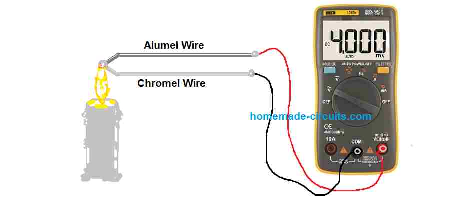
In this 100 °C to 1000 °C thermocouple temperature meter circuit project, a couple of special alloy metals (Chromel/Alumel) are needed with their ends joined or fused together. For example, one of ends of a CHROME wire and an Aluminum wire could be twisted tightly and the other ends connected to a millivolmeter.
Now If you heat the twisted ends of the wires, you will find a tiny amount of electricity being generated across the free ends of the wires and a deflection appearing on the meter needle.
However, unlike a thermistor, a thermocouple response is not dependent on the amount of heat applied to the fused ends, rather the meter reading will be proportionate to the heat difference between the twisted fused ends of the wires and the ends that are joined to the meter.
The twisted or the fused ends of the thermocouple wire is called the "hot end" and the opposite sides ends are called the "cold ends".
Therefore the electrical potential developing across the cold ends is actually proportionate to the difference between the temperature at the hot end and the cold end of the thermocouple wire assembly.
For example, suppose if we find the meter reading increasing at a rate of 4 mV per 100 °C applied at the fused ends of the wires, and the temperature at the cold end connected to the meter is 22 °C, then with the meter reading at 4 mV would indicate that the actual temperature across the fused end is 100 + 22 = 122 °C.
Circuit Description
The figure of a thermocouple meter circuit shown below is probably the simplest of its kind. It employs a single IC 741 op amp as the active device, a few resistors and a mA meter for displaying the temperature reading.
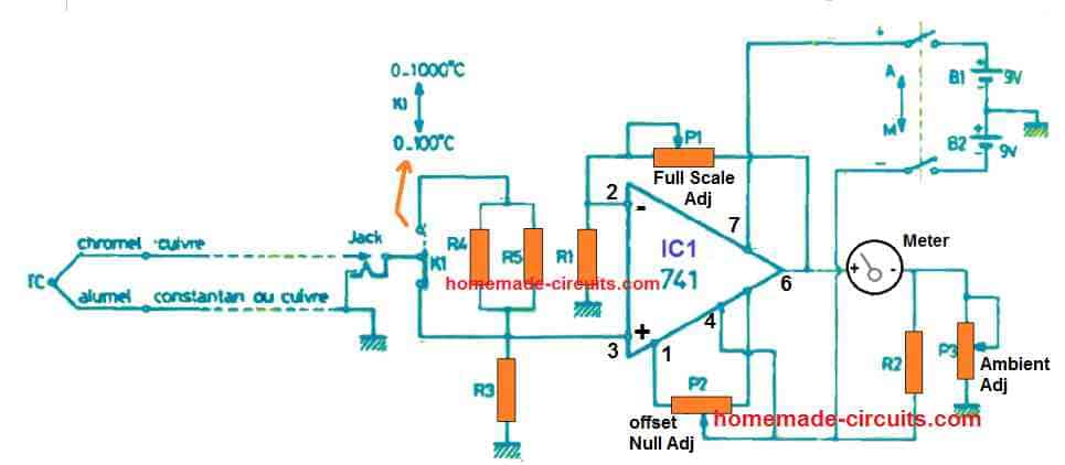
The power is applied from a couple of 9 V PP3 batteries. THe gain of the meter is adjusted and set for all the temperature ranges universally through the preset P1. This setting is done depending on the range and value of the mA meter.
The preset P2 is used for adjusting the offset output voltage from the IC 741 op amp. It is adjusted until the needle is pushed to exact zero mark, while the system is not detecting any temperature.
The resistive divider created using R3 and the preset P3 enables the ambient temperature correction adjustment for the meter.
This simple thermocouple temperature meter circuit features two handy temperature ranges to select from, one is 0 to 100, and the other is 0 to 1000. This range cn be selected with an quick toggling of the selector switch K1.
The Chromel/Alumel thermocouple sensor input is plugged into the circuit through an ordinary 3.5 mm jack, connected to the selector switch K1.
When the thermocouple (TC) is plugged into K1, it shorts circuits the non-inverting input of the op amp to ground.
Next, if we remove the TC from K1, the (+) input of the op amp is removed from the ground, an at this meter the meter must show zero.
If it doesn't then adjust the offset null preset P2 until the needle reaches the zero point on the meter.
After this connecting the TC to the K1 socket, must keep the meter needle at zero until a temperature difference is created across the two ends of the TC.
In case you find a slight deviation on the meter needle side due to ambient temperature difference across the "hot end" and "cold end" of the TC, this may be corrected by carefully adjusting the P3 preset, until the needle indicates the ambient temperature on the meter.
Now, your thermocouple meter is all set for use.
How to Set Up
In the above paragraph I have explained the basic procedure for setting up the 3 presets of the unit. The following explains the precise method of setting up the thermocouple temperature meter circuit.
- Check the mechanical zero of the millivolmeter
- Adjust P1 and P2 presets at halfway and adjust the P3 preset at zero (ground)
- Remove the TC from the jack plug and switch ON power supply.
- Adjust the preset P2, using a screwdriver so that the meter needle settles to the zero mark
- Adjust the preset P3 until the meter needle displays or indicates the exact ambient temperature or the room temperature.
- Now, insert the TC to the jack socket and immerse the fused tip of the TC in very hot water, at a known temperature between 100 °C and 1000 °C
- Now very carefully adjust the preset P1 until the meter needle indicates the correct temperature on the calibrated dial.
Parts List
- 1/4 MFR 1%
- R1 = 1 k
- R2 = 1.5 k
- R3 = 150 Ω
- R4 = R5 = 2.7 k
- P1 = 100k potentiometer
- P2 = 10k potentiometer
- P3 = 47 Ω potentiometer
- IC1 = 741 or any other standard op amp
- Meter = Can be any 0 to 100 mV meter
- K1 = single slide switch
- 1 Bipolar switch or a double switch (slide or lever)
- 1 jack socket 3.5 mm
- 1 jack plug 3.5 mm
- 2 sockets for small 9 V batteries
- 2 miniature 9 V batteries PP3
- 1 printed circuit 66 x 40 mm to be made
- 8 terminals for printed circuit
- 1 Chromel/Alumel thermocouple
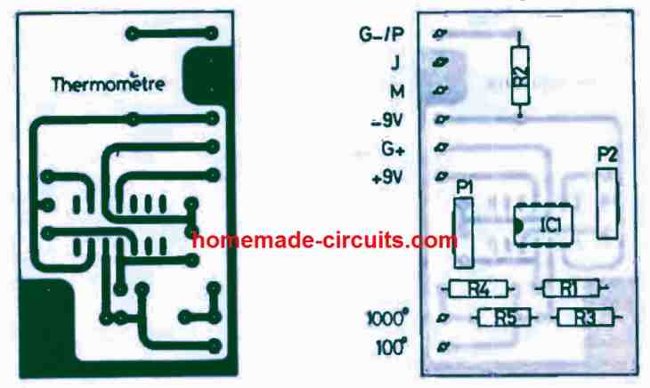
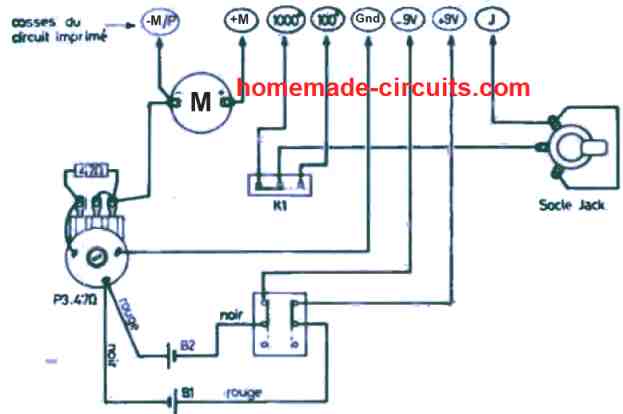
PCB Design
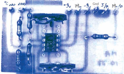
Wiring Layout
Another Simple Thermocouple Amplifier Circuit
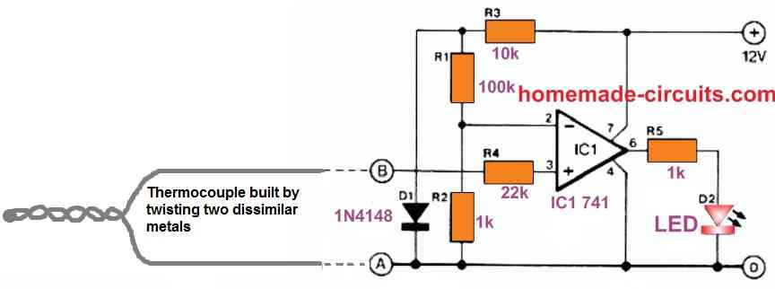
A thermocouple usually comprises of two different metals soldered or welded together at one end, in this case iron and constanan.
When the temperature at the weld fluctuates, the e.m.f. generated across terminals A and B is applied to the non-inverting input of comparator ICI.
The e.m.f. is compared to a 0.7 V reference voltage provided to the opamp's inverting input. The potential across terminals A and B is similarly 0.7 V when the temperature at the thermocouple's weld is around 150 °C.
The comparator subsequently switches, causing the LED to illuminate, signalling that the intended temperature threshold is reached. The constantan terminal must be attached to A, while the iron terminal must be soldered to B.


Comments
WOW a very interesting place.
Since I spent most of my life working at IBM my ability to create a workable little system is pretty weak. Anyway I studied when there were only germanium transistors and they didn’t know if they would help anyone. Thank goodness for sand.
So, maybe you can help. Deep breath. I live in an apartment building with solar collectors on the roof and a heat exchanger in the hot water cylinder. The problem is if you need hot water and switch on the hot water cyclinder heater and the solar building heating system pump starts to work you are basicly heating the water cylinders in the building. I want to add a electric water tap with a very slow dribble of water around it so the electrical water tap is operated (closed) when the temperature coming out of the heat exchanger is hotter than the temperature of the water going in. If the temperature of the incoming heat exchange water is hotter then the electrical tap will open again.
So far I have thermocouples with an output of 7mv or so 🙂 and an IC 741 with a maybe 5volt output to a TOLAKO 5volt module operating the the 220v electrical tap.
My head is full of values that don’t seem to work out.
Any help would be greatly appreciated. Seems nobody makes a kit like this and that surprises me.
Thank you for your question and the detailed explanation.
If you are trying to figure out how to connect the 741, thermocouple and the relay for implementing the operations, you can do it in the following manner:
https://www.homemade-circuits.com/wp-content/uploads/2024/03/hot-water-tap-controller-circuit.jpg
Let me know if you have any further questions.
Bro I want to make a k type thermocouple amplifier for my soldering iron using ina128.
Kindly provide a suitable circuit. Thanks
Hi Bivash, presently I do not have this circuit diagram with me, but I will try to get it and inform you once I find it.
Thanks bro. In making a diy soldering station. Operated by Arduino nano. So I need a thermocouple amplifier suitable for my soldering iron (280°c-480°c).
I have found ina128 to be much accurate and specially made for such instrumental amplifing jobs. So I wanna make a thermocouple amplifier.
Well I have a basic diagram though. I got that from tye datasheet. But it will cost my much. Looking for a cheaper circuit.
Based on resistors diodes capacitor etc.
Please help
Bivash, I think you can try the 741 IC based circuit explained in the above article.
It is also a K type thermococuple since it utilizes two different types of metals without using iron.