• Skip to main content
  • Skip to primary sidebar

Homemade Circuit Projects

Need circuit help? Post them in the comments! I've answered over 50,000!

Blog | Categories | About | Hire Me | Contact | Calculators-online
You are here: Home / Voltage Control and Protection / USB 5V To 24V DC to DC Buck, Boost Power Regulator Module

USB 5V To 24V DC to DC Buck, Boost Power Regulator Module

Last Updated on August 11, 2026 by Swagatam 2 Comments

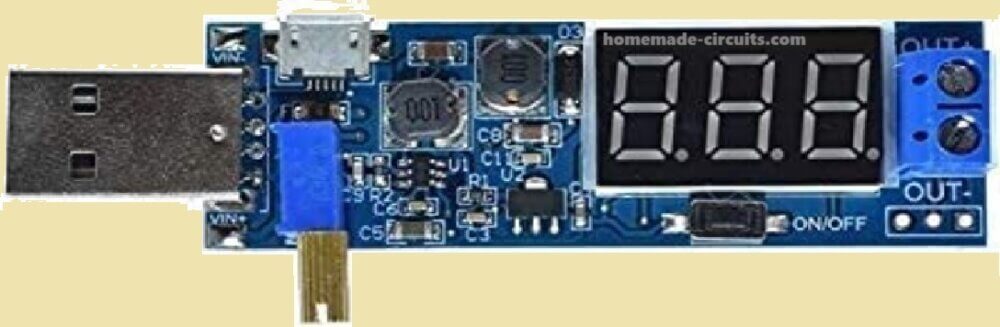
This is a USB 5V to 24V Adjustable Buck/Boost Converter Module and it helps us step up or step down an input voltage into a higher or lower voltage, which we can adjust as needed.

Table of Contents
  • Inputs – Where We Give Power
  • Output Voltage – What We Get as Output
  • Display and Controls – How We Use It
    • Where We Can Use It – What It is Good For
    • Some Important Things to Remember

Now let us go through everything in detail step by step.
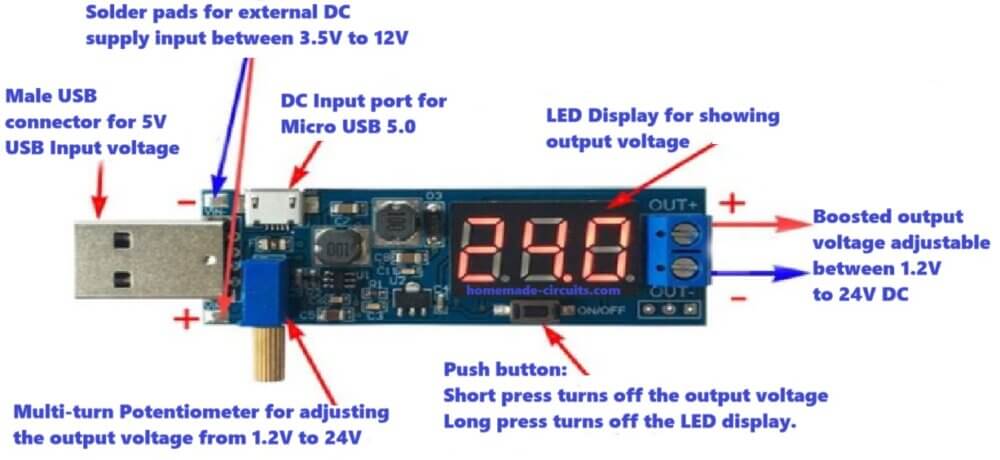
DC To DC USB 5V To 24V Boost Power Regulator Module wiring diagram

Inputs – Where We Give Power

Now we got three ways to power this module.

USB Head Input (5V):

Here we just plug it into a normal USB port from a laptop, PC, power bank, or adapter. But USB usually gives 5V only, so this is our most common input option.

Micro USB 5.0 Input:

Ok, here we got another way! We can power it with a Micro USB cable. So if we have a phone charger or a USB adapter then we just connect it here, and it works fine.

Solderable Pad Input (3.5V – 12V):

Now, this one is different. If we do not want to use USB power then we can solder wires to these pads and give power from a battery or a DC adapter.

But we need to give between 3.5V and 12V. Less than that, it will not work... more than that, it may be dangerous for the module.

Output Voltage – What We Get as Output

Adjustable Output Voltage (1.2V – 24V):

So, here is the interesting thing! We can change the output voltage using this multi-turn precision potentiometer (the round shaft that we rotate). If we turn it clockwise, then voltage goes up slowly. If we turn it counterclockwise, then the voltage goes down slowly.

But check this one important thing, see this is a buck and boost converter both, so the output voltage can be lower or equal or higher than the input voltage.

For Example: Let us say we put 5V input, then we can adjust it from 5V to 24V and we can also go down till 0.6V output.

Display and Controls – How We Use It

Digital Display:

Now, we got this nice screen that shows us the available output voltage. So, no need for an extra multimeter, this display helps us check the voltage directly. Pretty useful!

ON/OFF Button:

Ok, this button does two things: If we short press it, then it turns the output ON/OFF. If we long press it, then it turns off the display but the module keeps working.

Where We Can Use It – What It is Good For

  • If we need to charge devices that need a different voltage (like 9V, 12V, or 19V gadgets).
  • If we are working on some DIY electronics project and need a variable voltage source.
  • If we want to power small DC motors, LED strips, or Arduino boards with adjustable voltage.
  • If we have a battery that gives lower voltage and we want to boost it up for some circuit.

Some Important Things to Remember

Current Limit: How much current it gives depends on the input power.

Heat Issue: If we use high voltage, it may get hot, so we should check that.

USB Current Limit: Normal USB ports give 500mA – 2A, so if we want more power, then we need a stronger power source.
DC To DC USB 5V To 24V Boost Power Regulator Module

You'll also like:

  • mains overload protection 1Mains AC Overload protection Circuit for Voltage Stabilizers
  • boost converter working modelSimple Boost Converter Circuit Diagrams using Transistors
  • Do We Need a Freewheeling Diode Across the Inductor in Boost Converter?
  • Make this Single MOSFET Solid-State Relay SSR circuit

Filed Under: Voltage Control and Protection Tagged With: 24v, Boost, DC, Power, Regulator, USB

About Swagatam

I am an electronics engineer and doing practical hands-on work from more than 15 years now. Building real circuits, testing them and also making PCB layouts by myself. I really love doing all these things like inventing something new, designing electronics and also helping other people like hobby guys who want to make their own cool circuits at home.

And that is the main reason why I started this website homemade-circuits.com, to share different types of circuit ideas..

If you are having any kind of doubt or question related to circuits then just write down your question in the comment box below, I am like always checking, so I guarantee I will reply you for sure!


Previous Post: « XL3608 5V, 9V,12V DC, 2 Amp Boost Converter module
Next Post: DC-DC Boost Module (0.9V~5V) to 5V 600mA USB Step-up Board »

Reader Interactions

Questions & Answers

Total Posts: 2
Newest Oldest
AntoDas8
August 11, 2026 • 1 week ago #211780

I have this module and it is a buck-boost converter, not a boost converter. Please change the error kindly

Reply
SwagatamAdmin
August 11, 2026 • 1 week ago #211784

OK thanks for notifying this. I have updated the article accordingly, but due to site cache it won’t show up immediately, it may take 24 hours for the changes to become live…

Reply

Need Help? Please Leave a Comment! We value your input—Kindly keep it relevant to the above topic! Cancel reply

Your email address will not be published. Required fields are marked *

Primary Sidebar


Categories

  • Arduino Projects (95)
  • Audio and Amplifier Projects (134)
  • Automation Projects (18)
  • Automobile Electronics (104)
  • Battery Charger Circuits (90)
  • Datasheets and Components (109)
  • Electronics Theory (150)
  • Energy from Magnets and Earth (41)
  • Games and Sports Projects (11)
  • Grid and 3-Phase (20)
  • Health related Projects (27)
  • Home Electrical Circuits (13)
  • Indicator Circuits (16)
  • Inverter Circuits (100)
  • Lamps and Lights (163)
  • Meters and Testers (72)
  • Mini Projects (28)
  • Motor Controller (68)
  • Oscillator Circuits (30)
  • Pets and Pests (15)
  • Power Supply Circuits (91)
  • Remote Control Circuits (50)
  • Security and Alarm (65)
  • Sensors and Detectors (107)
  • SMPS and Converters (46)
  • Solar Controller Circuits (62)
  • Temperature Controllers (44)
  • Timer and Delay Relay (50)
  • Voltage Control and Protection (44)
  • Water Controller (37)
  • Wireless Circuits (31)


Circuit Simulator

circuit simulator image


Subscribe to get New Circuits in your Email


Other Links

  • Privacy Policy
  • Cookie Policy
  • Disclaimer
  • Copyright
  • Videos
  • Sitemap

People also Search

555 Circuits | 741 Circuits | LM324 Circuits | LM338 Circuits | 4017 Circuits | Ultrasonic Projects | SMPS Projects | Christmas Projects | MOSFETs | Radio Circuits | Laser Circuits | PIR Projects |


Recent Comments

  • Swagatam on Electronic Circuit Projects, Tutorials, and Practical Engineering Solutions
  • Swagatam on Electronic Circuit Projects, Tutorials, and Practical Engineering Solutions
  • Swagatam on 4 Simple Battery Desulfator Circuits Explored
  • Swagatam on 4 Simple Battery Desulfator Circuits Explored
  • Swagatam on PIR Controlled Solar Garden Light Circuit

Social Profiles

  • Twitter
  • YouTube
  • Instagram
  • Pinterest
  • My Facebook-Page
  • Stack Exchange
  • Linkedin

© 2026 · Swagatam Innovations