This passive PFC calculator does not use any MOSFET or PWM or switching frequency. It only uses 50 Hz mains and it only works with inductors and capacitors, so the only thing that matters is the reactance of the inductor and the reactance of the capacitor at the mains frequency. That is why the calculator uses only AC voltage, AC frequency, capacitor value and inductor value.
Simple Passive PFC Calculator
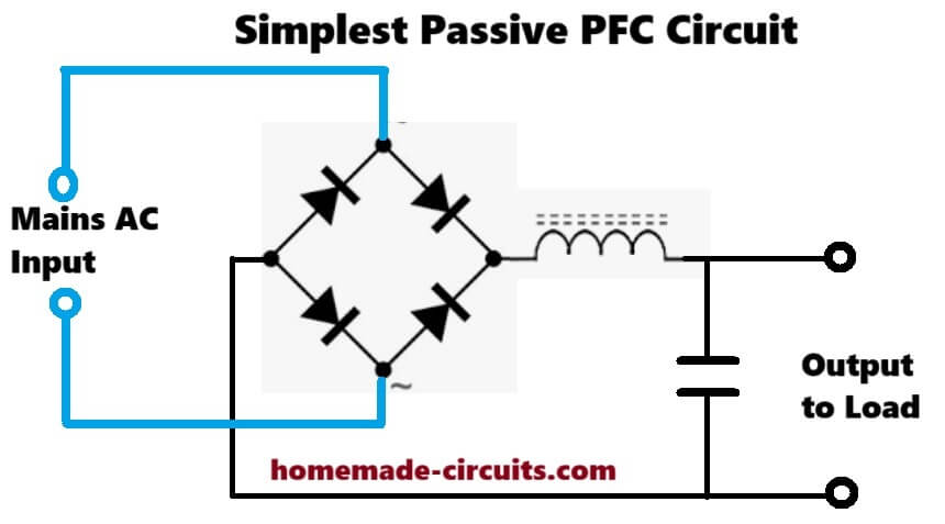
Circuit Diagram
How it Works
We see that this PFC diagram is showing the most simple passive PFC idea, so the mains AC is entering from the left side and then it is going inside a full bridge rectifier.
Function of Bridge Rectifier
We know that this bridge rectifier is taking the AC and converting it into pulsating DC, so when the AC goes positive then two diodes conduct and when AC goes negative then the other two diodes conduct, so you always get a unidirectional DC at the right side of the bridge.
Function of Inductor
Then we see that after this bridge rectifier there is one big inductor connected in series with the output line, so we understand that this inductor is the actual PFC element.
We know that when the current tries to suddenly rise and fall due to the pulsating rectified waveform then the inductor opposes this sudden change.
So now what happens is that the inductor tries to slow down the current ripple and tries to make the current waveform more smooth and more sinusoidal, so the current waveform becomes more in phase with the AC voltage.
That is why this is called power factor correction. The inductor forces the current to rise and fall slowly so it becomes closer to the voltage shape.
Function of Capacitor
Then we see at the end there is one big capacitor connected to ground from the positive line.
We know that this capacitor is only for filtering and energy storage, so when the load is taking power then the capacitor gives the required stable DC and when the bridge rectifier pulses come then the capacitor gets charged and maintains the voltage, so the inductor smooths the current and the capacitor smooths the voltage.
Conclusion
So we can say that the AC first becomes pulsating DC through the bridge, then the inductor shapes the current wave to make it slow and sinusoidal like, then the capacitor filters the final DC and supplies the load.
It means that this is the most basic passive PFC where we only use the natural property of the inductor to improve power factor without any PWM or MOSFET control.
Manual Calculations using Formulas to Counter Check Calculator Output
- Vpeak (mains peak)
Vrms = 220.00 V
sqrt(2) = 1.4142135623730951
Vpeak = Vrms * sqrt(2) = 220 * 1.4142135623730951 = 311.127 (rounded of) V
(keep as 311.127105721081 V for precision) - DC bus used (auto method in calculator)
We used diode drops ≈ 2 × 1.1 V = 2.2 V
Vbus = Vpeak − 2.2 = 311.127105721081 − 2.2 = 308.927105721081 V - DC load current I_dc = Pout / Vbus
Pout = 3000 W
I_dc = 3000 / 308.927105721081
Divide step by step:
3000 ÷ 308.927105721081 = 9.711 (rounded) A
More precisely I_dc = 9.711012... A.... displayed as 9.71 A. - Required total bulk capacitance (for peak-to-peak ripple ΔV = 5 V)
Formula: C_total = I_dc / (2 · fline · ΔV)
fline = 50 Hz, ΔV = 5 V
Denominator = 2 * 50 * 5 = 500
C_total = 9.711012... / 500 = 0.019422024... F
Convert to µF: 0.019422024 * 1e6 = 19,422.024 µF
Rounded = 19,425 µF (our calculator showed 19,425 µF)...... so matches within rounding. - Required PFC inductor (series choke) for peak charge limit I_charge = 20 A
Xpfc = Vpeak / I_charge = 311.127105721081 / 20 = 15.55635528605405 Ω
Lpfc = Xpfc / (2π fline) = 15.55635528605405 / (2 * π * 50)
2π×50 = 314.1592653589793
Lpfc = 15.55635528605405 / 314.1592653589793 = 0.049526 (H)
Convert to mH: 0.049526 * 1000 = 49.526 mH
Rounded = 49.51 mH (our calculator showed 49.51 mH) — so it matches.
practical rounded numbers
- Vpeak ≈ 311.13 V
- Vbus used ≈ 308.93 V
- DC Load Current I_dc ≈ 9.71 A
- Required total bulk capacitance ≈ 19,420 µF (≈ 19.4 mF) — our calculator 19,425 µF is fine.
- Required series PFC inductor Lpfc ≈ 49.53 mH — our calculator 49.51 mH is fine.
Notes and quick practical tips
- The bulk cap result ≈ 19.4kµF means use multiple caps in parallel (example 5×4700 µF @400V = 23.5kµF is a practical choice).
- Lpfc ≈ 49.5 mH is large and heavy for 3 kW. If space/weight is a problem, use NTC/soft-start or accept higher I_charge.
- All manually arithmetic matches exactly as calculator outputs and are correct to displayed precision.


Need Help? Please Leave a Comment! We value your input—Kindly keep it relevant to the above topic!