It is possibly the smallest LED flasher to date, which is able to flash an LED ON/OFF infinitely using a single transistor, a resistor, and a capacitor.
Can you imagine making a great looking LED flasher or blinker with just a single transistor and a couple of other passive parts?
That's exactly what I have explained in this post! This is perhaps the world's simplest and the tiniest LED flasher you can get!
How it Works
I came across this phenomena some eight years ago (2006), accidentally, while trying to make a smallest possible motorcycle side indicator flasher, and was surprised by the phenomenon.
However, then I realized that the phenomenon was already discovered by Mr. Dick Cappels while investigating the negative resistance theory in BJTs by the Japanese researcher Mr. Reona Esaki (Aka Leo).
Reona Esaki's thesis work in the relevant field and on tunnel diodes ultimately won him the Nobel Prize in 1972.
That looks too good to be true, however the following diagram will simply prove that it's really possible to create a working LED flasher circuit using just one general purpose transistor as the main component.
At that time, I was unaware that this was occurring as a result of the transistor's negative resistance characteristics.
The circuit actually exploits the negative resistance factor in transistors to produce the blinking effect.
I'll be soon writing a comprehensive article on this and we'll see there how the concept can be modified in many different ways.
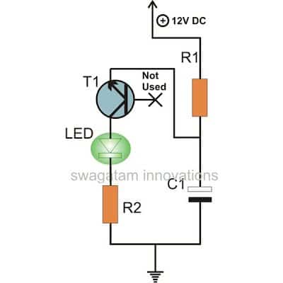
Parts List for the proposed single transistor LED flasher circuit
- R1 = 2K7,
- R2 = 100 Ohms,
- T1 = BC 547,
- C1 = 100 uF to 470 uF
- LED = Any Type, any color
The flashing rate could be varied either by changing the value of R1 or C1 or both together. But the supply voltage not be less than 9V otherwise the circuit might fail to work correctly.
You may also love to read this article: Blinking LED Circuit using LDR
Circuit Diagram
Calculating the LED Flashing Frequency
You can use the following formula for approximately calculating the LED ON/OFF blinking rate
Frequency (f) ≈ 1 / (2.1 * R * C)
Where:
- R is the resistance in ohms
- C is the capacitance in farads
This formula gives us a rough idea of what the flashing frequency might be. But the actual frequency can be affected by a hand full of different factors, for example like the specific components you are using in the circuit, the voltage of the power supply and also the temperature.
To adjust the flashing rate:
- Increase the resistance (R): If we make the resistance higher, it will take longer for the capacitor to charge up which means the flashing rate will be slowed down.
- Decrease the capacitance (C): On the opposite side, if we lower the capacitance vaalue, the capacitor will charge up faster causing the flashing rate to speed up.
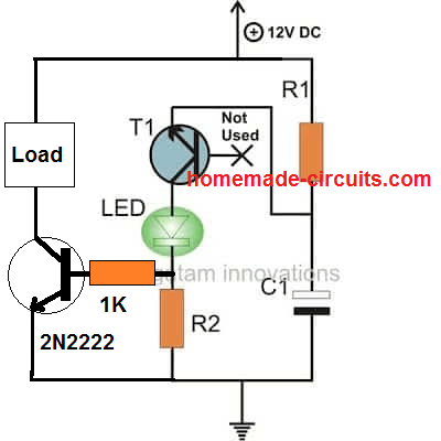
Connecting an External Transistor for Higher Loads
Video Clip:
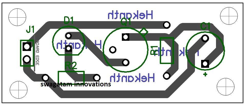
PCB Design


Hello dear friends
It is a very good and economical circuit, I have made it, I suggest you make several of it using different R&C. As a result, the frequencies of each will be different and when they are together in one place, they create a beautiful set with unpredictable combinations. Also, using two transistors (one oscillator which is seen in the circuit above and oneA current boosting transistor (preferably a 2N2222) can drive up to 4 LEDs. If 4 circuits are made with 4 LEDs, we will have 16 attractive LEDs. To boost, remove the LED and replace it with a 100k resistor, and connect the base of the boosting transistor to the collector of the oscillator transistor.
thanks
Sounds like a great idea, thanks for your interesting feedback!
Hi Swagatam,
In the single-transistor circuit, if there’s no connection to the base of the transistor, isn’t it just a diode?
Hi Tom,
For the BJT to work like a diode, its base must be connected to its collector.
Here the base is open, and furthermore the emitter is connected to the positive, which is rather supposed to be connected to ground in a standard configuration, so the design is indeed weird.
Thanks for the clarification. We’re agreed that the design is a little weird. 🙂
Yep :p, thanks for your feedback…