• Skip to main content
  • Skip to primary sidebar

Homemade Circuit Projects

Need circuit help? Post them in the comments! I've answered over 50,000!

Blog | Categories | About | Contact | Calculators-online
You are here: Home / Datasheets and Components / AMS1117 1A LDO Voltage Regulator IC – 3.3V, 1.8V, 2.5V, 5V Regulators

AMS1117 1A LDO Voltage Regulator IC – 3.3V, 1.8V, 2.5V, 5V Regulators

Last Updated on April 25, 2025 by Swagatam 1 Comment

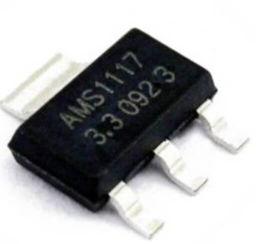
In this post I will be talking about one famous voltage regulator IC called AMS1117. It is a 1 Amp Low Dropout (LDO) Linear Voltage Regulator and we can get it in both fixed output types and also adjustable output version. It is super small, easy to use and available in SOT-223 package mostly, which means flat-type with three legs.

Table of Contents
  • What this AMS1117 does actually?
  • Types of AMS1117 You Can Get
  • Pinout Details of AMS1117 (Same for all versions)
  • Internal Working – Simple Talk
  • How to Set Output in Adjustable Version
  • Current and Voltage Ratings
  • How to Keep it Cool
  • Where We Use AMS1117?
  • Example Application Circuit (Fixed Voltage Output)

If you are making Arduino stuff or ESP projects or any 3.3V or 5V gadgets then this AMS1117 is like our bread and butter, right!

ams1117 ldo regualtor

What this AMS1117 does actually?

So this chip, what it does is, it takes higher voltage at input (like 5V, 12V, etc) and gives a lower stable voltage at output like 3.3V, 5V, 1.8V, etc. That too with low dropout means it can work even if input is just a bit higher than output.

For example if we use AMS1117-3.3 it will give 3.3V output even if input is just like 4.5V or 5V. That is what we call LDO – Low Dropout, unlike old 7805 which needs 7V+ input for 5V output.

Types of AMS1117 You Can Get

We get different versions of this chip:

VariantOutput VoltageAdjustable?
AMS1117-5.05.0V FixedNo
AMS1117-3.33.3V FixedNo
AMS1117-2.52.5V FixedNo
AMS1117-1.81.8V FixedNo
AMS1117 (Adj)AdjustableYes (1.25V to 12V max)

So if you want simple plug-n-play voltage then just take fixed version. But if you want to set voltage as per your circuit, then go for the adjustable version.

Pinout Details of AMS1117 (Same for all versions)

ams1117 pinout details

Usually 3 pins + tab (heat sink pad):

  • Pin 1 (ADJ or GND) → For fixed version, this is GND.
    For adjustable version, this is Adjust pin.
  • Pin 2 (Vout) → Output voltage.
  • Pin 3 (Vin) → Input voltage (should be 1.1V more than output min).
  • Tab → Internally connected to Vout, used for heat sinking.

Internal Working – Simple Talk

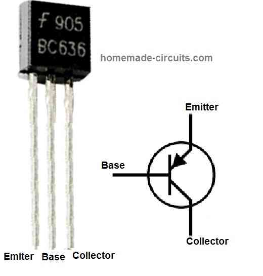
Inside this AMS1117 there is a voltage reference (1.25V), some error amplifiers, and a series pass transistor. When input comes, then it compares the voltage and adjusts the pass transistor to give steady output.

In adjustable one, it keeps 1.25V between Vout and Adjust pin, so we can change output using external resistors.

How to Set Output in Adjustable Version

We use this formula:

Vout = 1.25 × (1 + R2 / R1)

We can also add a capacitor for better stability.

AMS1117 regulator circuit diagram for adjustable output voltages

Example: If we want 5V output, we can select:

R1 = 220 ohms

R2 = 660 ohms

Then Vout = 1.25 × (1 + 660 / 220) = 5V approx

We can use 10K trimmer as R2 to adjust it easily.

Current and Voltage Ratings

  • Max Output Current: 1 Amp (with heatsink).
  • Max Input Voltage: 15V (but better to keep it under 12V for safety).
  • Dropout Voltage: Around 1.1V when load is 800mA to 1A.
  • Power Dissipation: Depends on heatsink and PCB pad.
  • Thermal Shutdown and Short Circuit Protection: Yes built-in.

How to Keep it Cool

This thing gets hot if you draw full 1A and drop high voltage (difference between input and output voltage).

Say, you input 12V and take 3.3V at 1A →

Then that means 12V - 3.3V = 8.7V × 1A = 8.7 Watts heat, that is equivalent to = fire hazard.

So use it only for small loads (under 500mA) or use big copper pad, heatsink or go for switching regulator like buck converter.

Where We Use AMS1117?

  • ESP8266 / ESP32 3.3V power supply.
  • Arduino sensors that need 3.3V.
  • Low-noise analog circuits.
  • Battery-powered circuits needing stable voltage.
  • Raspberry Pi peripherals.
  • Custom PCBs and breadboard projects.

Example Application Circuit (Fixed Voltage Output)

AMS1117 regulator circuit diagram for fixed output voltages such as 1.8V, 2.5V. 3.3V, 5V

You'll also like:

  • 1.  BC636 Transistor Datasheet [45 V 1 Amp PNP Transistor]
  • 2.  IC 4049 Datasheet, Pinout Function, Application
  • 3.  AC 220V/120V Mains Surge Protector Circuits
  • 4.  Low Power MOSFET 200mA, 60 Volts Datasheet
  • 5.  IC 4013 Datasheet, Pinout Details
  • 6.  L293 Quad Half-H Driver IC Pinout, Datasheet, Application Circuit

Filed Under: Datasheets and Components, Voltage Control and Protection Tagged With: AMS1117, LDO, Regulator, Regulators, Voltage

About Swagatam

I am an electronics engineer and doing practical hands-on work from more than 15 years now. Building real circuits, testing them and also making PCB layouts by myself. I really love doing all these things like inventing something new, designing electronics and also helping other people like hobby guys who want to make their own cool circuits at home.

And that is the main reason why I started this website homemade-circuits.com, to share different types of circuit ideas..

If you are having any kind of doubt or question related to circuits then just write down your question in the comment box below, I am like always checking, so I guarantee I will reply you for sure!

Previous Post: « Single Ended nOOds, 300mm long Flexible LED Filament, Warm White 3V
Next Post: IC LM7912, -12V Negative Voltage Regulator Explained »

Reader Interactions

Comments

  1. Daouda says

    May 2, 2025 at 6:11 am

    bonsoir monsieur comment allez-vous. s’il vous plait je peux avoir un schéma électronique d’un contrôleur des phases trophées. merci

    Reply

Need Help? Please Leave a Comment! We value your input—Kindly keep it relevant to the above topic! Cancel reply

Your email address will not be published. Required fields are marked *

Primary Sidebar

circuit simulator image

Subscribe to New Posts

Categories

  • Arduino Projects (89)
  • Audio and Amplifier Projects (132)
  • Automation Projects (17)
  • Automobile Electronics (101)
  • Battery Charger Circuits (83)
  • Datasheets and Components (104)
  • Electronics Theory (143)
  • Free Energy (37)
  • Games and Sports Projects (11)
  • Grid and 3-Phase (19)
  • Health related Projects (25)
  • Home Electrical Circuits (12)
  • Indicator Circuits (14)
  • Inverter Circuits (88)
  • Lamps and Lights (142)
  • Meters and Testers (69)
  • Mini Projects (46)
  • Motor Controller (64)
  • Oscillator Circuits (27)
  • Pets and Pests (15)
  • Power Supply Circuits (108)
  • Remote Control Circuits (50)
  • Security and Alarm (64)
  • Sensors and Detectors (101)
  • Solar Controller Circuits (59)
  • Temperature Controllers (42)
  • Timer and Delay Relay (49)
  • Transmitter Circuits (29)
  • Voltage Control and Protection (39)
  • Water Controller (36)

Other Links

  • Privacy Policy
  • Cookie Policy
  • Disclaimer
  • Copyright
  • Videos
  • Sitemap

People also Search

555 Circuits | 741 Circuits | LM324 Circuits | LM338 Circuits | 4017 Circuits | Ultrasonic Projects | SMPS Projects | Christmas Projects | MOSFETs | Radio Circuits | Laser Circuits | PIR Projects |

Social Profiles

  • Twitter
  • YouTube
  • Instagram
  • Pinterest
  • My Facebook-Page
  • Quora
  • Stack Exchange
  • Linkedin
  • Recent Comments

    • Swagatam on DIY 100 Watt MOSFET Amplifier Circuit with PCB
    • Swagatam on 10 LED Tachometer Circuit Diagram
    • Göran on 10 LED Tachometer Circuit Diagram
    • Swagatam on Wideband Amplifier Circuits
    • Swagatam on 10 LED Tachometer Circuit Diagram

    © 2025 · Swagatam Innovations

    We use cookies to serve ads, YouTube and analytics. Please accept to continue.