• Skip to main content
  • Skip to primary sidebar

Homemade Circuit Projects

Need circuit help? Post them in the comments! I've answered over 50,000!

Blog | Categories | About | Contact | Calculators-online
You are here: Home / Solar Controller Circuits / Solar Drip Irrigation Circuit for Indoor Gardens

Solar Drip Irrigation Circuit for Indoor Gardens

Last Updated on September 3, 2020 by Swagatam 3 Comments

In this post I have explained a water level controller circuit which can be used for implementing an unmanned continuous drip irrigation to a home based garden. The idea was requested by Mr. Sandipan.

Table of Contents
  • Technical Specifications
  • The Design
  • Circuit Operation
  • Parts List for the discussed Solar drip irrigation for indoor gardens

Technical Specifications

I’m implementing a drip irrigation for my balcony garden. One part of it is to automatic fill water a 5 liter/10 liter vessel (this is source of water for drip irrigation) from a bigger water tank (When I’m not at home for longer period of time like 15 days).So I break this project into several steps as follows

  • 1.      Implementing drip irrigation using a 5 or 10 liter vessel (say V1) as source of water. Probably smaller vessel will reduce the water pressure.
  • 2.       Have an automatic water pumping system to fill the vessel V1 periodically based on the water level in vessel V1 from a bigger water tank. If V1 is full motor should goes off and if water level in Vessel V1 is low to a certain point, motor should start to fill the vessel V1. I want to implement this pumping system using a homemade 6 Volt DC motor (DIY water pump using a dc motor).
  • 3.       Implement solar charging system to recharge the 6 volt lead acid declarable battery (so that if I’m out of my town for even 30 days, the battery should have enough juice to drive my small  water pump).

I’m done with step 1. When I was searching water level based automatic water pump, I came across your website. Let me tell you one thing, YOU ARE DOING WONDERFUL JOB. Now every day I open your site at least once to see different innovations of yours. I have seen your project https://www.homemade-circuits.com/2011/12/how-to-make-simple-water-level.html#.But my requirement is a bit different as follows

  • a.       I need to operate a very small DC motor with 6 volt lead acid battery.
  • b.      At level below B (your diagram), motor should start fill my vessel V1 and when water reached at point A, motor should stop.
  • c.       Need to charge 6 volt lead acid battery using solar panel

Could you please help me with a circuit diagram?

Thank you

Sandipan

The Design

Referring to the figure below, the design may be configured by using a single IC 4093 for the proposed home drip irrigation and tank waer level control.

drip2Birrigation2Bcircuit

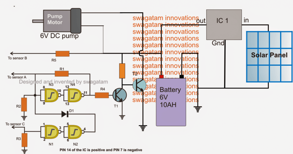
The water level control operation of the circuit is exactly identical to the one that's explained in this article.

As per the instructions provided in the above linked article, the motor is supposed to switch ON when the water in the tank has dropped below a particular level, which may be set by the user by installing sensor point C at the desired depth.

Circuit Operation

When the water pump starts, water is pumped inside the tank until it fills upto the brim, which prompts the motor to shut off through the signal as sensed by point A sensor.

The entire system can be seen powered through a 6V 10AH lead acid battery, which is charged by a suitably rated solar panel.

IC1 is a 7809 voltage regulator IC positioned to generate a regulated 9V charging input at a rate not exceeding 1 amp, to the battery.

Parts List for the discussed Solar drip irrigation for indoor gardens

  • R1 = 100K,
  • R2, R3 = 2M2,
  • R4, R5, R6= 1K,
  • T1 = BC547,
  • T2 = TIP122
  • IC1 = 7809
  • N1, N2, N3, N4 = 4093
  • Solar Panel = 12V/1amp
  • Motor = as per the intended specs

You'll also like:

  • 1.  How to Make a Simple Solar Inverter Circuit
  • 2.  Simple Vertical Axis Wind Turbine Generator Circuit
  • 3.  Water Flow Valve Timer Controller Circuit
  • 4.  Easiest Single Axis Solar Tracker System
  • 5.  Single Phase Jet Pump Controller Circuit
  • 6.  Control Two Submersible Pumps Alternately

Filed Under: Solar Controller Circuits, Water Controller Tagged With: Drip, Gardens, Indoor, Irrigation, Solar

About Swagatam

I am an electronics engineer and doing practical hands-on work from more than 15 years now. Building real circuits, testing them and also making PCB layouts by myself. I really love doing all these things like inventing something new, designing electronics and also helping other people like hobby guys who want to make their own cool circuits at home.

And that is the main reason why I started this website homemade-circuits.com, to share different types of circuit ideas..

If you are having any kind of doubt or question related to circuits then just write down your question in the comment box below, I am like always checking, so I guarantee I will reply you for sure!

Previous Post: « Transformerless Constant Current LED Driver Circuit
Next Post: Mosquito Killer Circuit with Window Trap »

Reader Interactions

Comments

  1. submersible pump NZ says

    September 3, 2020 at 6:36 pm

    This is such an attractive article about the solar drip irrigation system for indoor.This is one of the best write up. You will get all the information about the topic in this article. I am sure many people will come to read this in future.

    Reply
  2. c00e6752-9f70-11e3-b67b-000bcdcb5194 says

    July 6, 2017 at 4:11 am

    hi
    has this circuit been tested and proven to work?
    how can i make this work with a 12v pump and 12v batter?

    thanks
    g

    Reply
    • Swagatam says

      July 6, 2017 at 11:05 am

      yes this has been tested with a DC power supply.

      for 12V supply using a 15V solar panel, a 7812 IC for the IC1, and a 12V battery, and also a 12V pump…

      Reply

Need Help? Please Leave a Comment! We value your input—Kindly keep it relevant to the above topic! Cancel reply

Your email address will not be published. Required fields are marked *

Primary Sidebar

circuit simulator image

Subscribe to New Posts

Categories

  • Arduino Projects (89)
  • Audio and Amplifier Projects (132)
  • Automation Projects (17)
  • Automobile Electronics (101)
  • Battery Charger Circuits (83)
  • Datasheets and Components (104)
  • Electronics Theory (143)
  • Free Energy (37)
  • Games and Sports Projects (11)
  • Grid and 3-Phase (19)
  • Health related Projects (25)
  • Home Electrical Circuits (12)
  • Indicator Circuits (14)
  • Inverter Circuits (88)
  • Lamps and Lights (142)
  • Meters and Testers (69)
  • Mini Projects (46)
  • Motor Controller (64)
  • Oscillator Circuits (27)
  • Pets and Pests (15)
  • Power Supply Circuits (108)
  • Remote Control Circuits (50)
  • Security and Alarm (64)
  • Sensors and Detectors (101)
  • Solar Controller Circuits (59)
  • Temperature Controllers (42)
  • Timer and Delay Relay (49)
  • Transmitter Circuits (29)
  • Voltage Control and Protection (39)
  • Water Controller (36)

Other Links

  • Privacy Policy
  • Cookie Policy
  • Disclaimer
  • Copyright
  • Videos
  • Sitemap

People also Search

555 Circuits | 741 Circuits | LM324 Circuits | LM338 Circuits | 4017 Circuits | Ultrasonic Projects | SMPS Projects | Christmas Projects | MOSFETs | Radio Circuits | Laser Circuits | PIR Projects |

Social Profiles

  • Twitter
  • YouTube
  • Instagram
  • Pinterest
  • My Facebook-Page
  • Quora
  • Stack Exchange
  • Linkedin
  • Recent Comments

    • Swagatam on 10 LED Tachometer Circuit Diagram
    • Göran on 10 LED Tachometer Circuit Diagram
    • Swagatam on DIY 100 Watt MOSFET Amplifier Circuit with PCB
    • Swagatam on 10 LED Tachometer Circuit Diagram
    • Göran on 10 LED Tachometer Circuit Diagram

    © 2025 · Swagatam Innovations

    We use cookies to serve ads, YouTube and analytics. Please accept to continue.