Here we will learn how to use a NAND Gate Oscillator Calculator using CD4011 or any CMOS NAND gate IC.
This calculator will take values of:
- R = timing resistor (in ohms)
- C = timing capacitor (in µF)
- and give you:
- Output frequency in Hz
- Time period
- ON time
- OFF time (assuming 50% duty cycle square wave for simplicity).
NAND Gate Oscillator Calculator
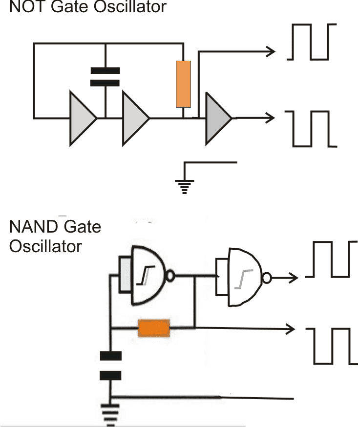
Here is how this NAND oscillator actually works. We take two NAND gates from a 4011 IC — like pin 1-2-3 and 4-5-6 — and connect them in a way that they keep toggling the output ON and OFF rapidly.
Circuit Wiring Details
First we take a 4011 NAND gate IC which has 4 gates inside.
We use 2 gates only for this oscillator, one gate to make the feedback oscillate and the second gate to buffer or invert it for clean square wave.
Now connect it like this:
- Pin 1 and 2 (inputs of 1st NAND) → tied together
- A resistor (R) → goes from pin 3 (output of 1st NAND) back to pin 1/2
- A capacitor (C) → goes from pin 1/2 to ground
This forms a delay feedback loop. When power is ON, capacitor charges through resistor and changes logic at inputs, which changes output, which again discharges the capacitor. This keeps flipping the state like a seesaw.
Then we take pin 3 (oscillating output) and feed it to another gate input, like pin 4 and 5 tied together, so output at pin 6 gives you final clean square wave.
Frequency Formula We Used
We used the standard NAND oscillator timing formula:
f = 1 / (1.38 × R × C)- R in ohms
- C in farads
- Result will be in Hz
- ON and OFF times assumed 50-50, so:
ON = OFF = 1 / (2 × f)Example
Say:
- R = 100k
- C = 0.1 µF
Then:
f = 1 / (1.38 × 100000 × 0.1e-6) ≈ 72.46 HzSo output blinks around 72 times per second.
Notes:
- Do not go too low with resistor or cap, IC might heat or output become messy.
- Always use ceramic or MKT cap (not electrolytic).
- Works from 5V to 15V (best at 9V or 12V).
- You can use all 4 gates for more buffering or logic expansion.
NAND Gate ICs (Standard + Schmitt Trigger)
The above calculator can be used for all the following ICs to calculate the frequency output of their oscillator configuration:
| IC Number | Type | Gates | Logic Family | Notes |
|---|---|---|---|---|
| CD4011 | Standard NAND | 4 | CMOS | Basic CMOS NAND, works great |
| CD4093 | Schmitt NAND | 4 | CMOS | Best for oscillators (clean switching) |
| 74LS00 | Standard NAND | 4 | TTL (LS) | Works, but avoid for analog timing (noisy) |
| 74HC00 | High-speed NAND | 4 | HC (CMOS) | Fast, low-power CMOS version |
| 74AC00 | Advanced CMOS | 4 | AC family | Very fast, not ideal for RC timing |
| SN74LVC1G00 | Single NAND | 1 | Tiny logic | Works but for surface mount only |
| CD4023 | Triple 3-input NAND | 3 | CMOS | Extra input, use carefully |
if you are building a simple RC oscillator then CD4011 and CD4093 are the kings. TTL ones like 74LS00 work but eat more power and glitch more often. 4093 is safest if you are going serious.
NOT Gate ICs (Inverters)
These ICs can be used in NOT gate oscillator configuration, where:
- R connects from output to input
- C goes from input to ground
- Output gives square wave
| IC Number | Type | Gates | Logic Family | Notes |
|---|---|---|---|---|
| CD4069UB | Unbuffered Inverter | 6 | CMOS | Best for oscillator use |
| CD4069B | Buffered Inverter | 6 | CMOS | Also works, slight edge in output drive |
| CD4049UB | Unbuffered Inverter | 6 | CMOS | Good, robust |
| CD4050 | Non-inverting buffer | 6 | CMOS | Not suitable (not inverter) |
| 74LS04 | TTL inverter | 6 | TTL | Works but noisy, avoid for slow oscillators |
| 74HC04 | Fast inverter | 6 | HC | CMOS fast version |
| 74HCT04 | TTL-compatible CMOS | 6 | HCT | For 5V logic |
| SN74LVC1G04 | Single inverter | 1 | Tiny | Tiny SMD version |
For NOT gate oscillator, always go with CD4069UB or CD4049UB, since they give perfect square wave even with high resistor/cap values. TTL ones like 74LS04 work only if you keep frequency high and R low.
Avoid These ICs for RC Oscillators:
| IC | Reason |
|---|---|
| CD4050 | Not an inverter, can't toggle on its own |
| 74ACxx | Way too fast, RC charging is unstable |
| Any Open-Collector Gates | Need external pull-ups, won’t oscillate by themselves |
| Buffers (like 74LS07) | Not logic inverters |
Best Choices for Reliable Oscillator
| Type | Best ICs | Why Good |
|---|---|---|
| NAND Gate | CD4011, CD4093 | Simple, reliable, easy to get |
| NOT Gate | CD4069UB, CD4049UB | Clean switching, noise-free |
| TTL Option | 74LS00, 74LS04 | Work, but power-hungry + noisy |
Comments
Hello and thank you very much for your work.
I already designed my oscillator using this component NC7WZ132K8X (2 NAND schmitt trigger gates) but it is advanced CMOS. As you said concerning the 74AC00 ”very fast, not ideal for RC timing”, do you think this component is also not ideal for oscillator ?
bye
Hey Degand, this NC7WZ132K8X is advanced CMOS and very fast but since it has Schmitt trigger input, that makes it good for RC oscillator. The Schmitt trigger makes clear switching thresholds and prevents unstable multiple transitions so the RC timing works okay. But if you use normal fast gate like 74AC00 without Schmitt then it will not work good for oscillator because it switches too fast without clean threshold. So this NC7WZ132K8X is fine for simple oscillator but do not expect precise frequency.
I am so glad you answered me. Thanks for your confirmation. I adapted your calculation based on the voltage thresholds of the NC7WZ132K8X. It’s okay, I don’ t need a precise frequency. First, I choose a tantalum capacitor but due to the leak current of this kind of capacitors I choose a MLCC X7R capacitor like you recommended.
Thank you so much,
Yves
It’s my pleasure! Sure, MLCC X7R type capacitor might be the right choice for your specific application…Please keep up the good work…