The discussed circuit is a solid state AC to DC voltage converter that will convert any AC input between 85 V and 250 V into a constant 310 V DC output. This kind of circuits are normally use in LCD TV sets for operating the system through inputs from 100 V AC to 250 AC.
The good thing about this circuit is that it does not depend on complex inductors and ferrite transformers as we have in SMPS circuits, rather it works with a perfectly solid-state design using only an FET, few diodes and a couple of capacitors.
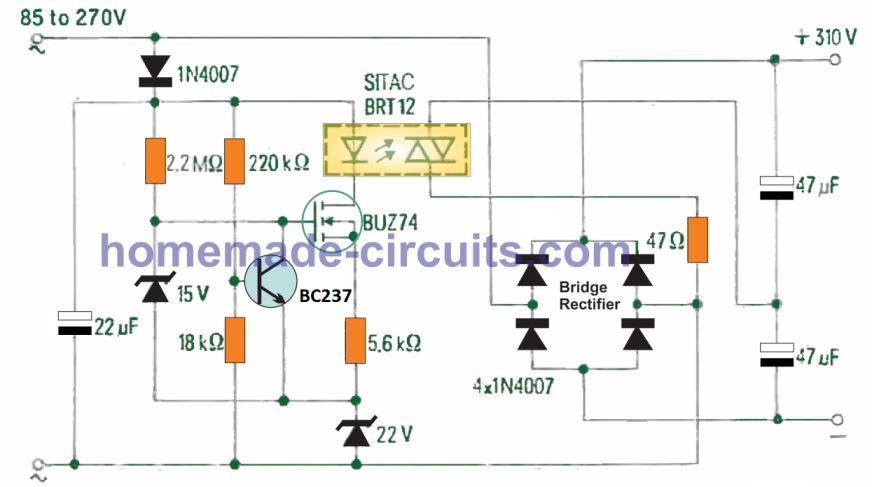
How the Circuit Works
Referring to the shown circuit diagram, the working of the unit can e understood with the following points:
The device BRT12 remains switched OFF as long as the input AC level is between 180 V and 270 V.
In this situation the bridge rectifier using 4nos 1N4007 diodes causes a full waev rectification of the input into a 300 V DC output, across the shown couple of high voltage filter capacitors.
However if a relatively low level input such as a 110 V DC is applied, the opto-triac BRT12 switches ON, causing a low resistance connection to develp across the bridge rectifier stage and the junction of the two filter capacitors.
This situation causes the bridge rectifier to turn into a voltage doubler, which enables the output to continue to be at around 300 V DC level.
The opto-triac is operated through a basic configuration comprosong of a SIPMOS FET BUZ74. The 22V zener is used for generating a reference voltage, and the netwrok using the 1N4001 diode and the 22 pF capacitor is used like a single phase rectifier stage.
When a low 110 V AC input is used, the BJT BC237 is turned OFF via the potential developed at the junction of the 220 k, 18 k resistive divider network.
This causes the FET to switch ON through a gate potential fixed by the 15 V zener diode.
The 5k6 series resistor ensures that the current through the BRT12 and the FET drain is limited to 2 mA. This is maintained even at relatively higher input voltages up to 175 V.
When the AC input exceeds this higher level, the base potential of BC237 increases to a level which is enough to switch it ON. This in turn effectively short-circuits the FET gate to ground, shutting OFF the FET and the current through the BRT12 opto.
Basically, the circuit can operate using AC inputs right from 50 V up to 300 V AC. The changeover happens at around 165 V input, when the opto-triac device BRT12 becomes non conductive. This turn OFF is implemented by the BJT BC237 and its base potential determined by the associated resistive divider circuit.
The main components that control the output at 310 V DC are the opto-triac BRT12, the bridge rectifier and the two output capacitors.
The maximum current capacity of this 110 V to 310 V converter circuit is 200 mA with ambient temperature not exceeding 45 °C. This current is sufficient for satisfactory working of most electronic gadgets.
Parts List
Resistors 1/4 watt 1% MFR
- 2M2 - 1no
- 220k - 1no
- 18k - 1no
- 5k6 - 1no
- 47 ohms - 1no
Capacitors
- 22uF/400V electrolytic - 1no
- 47uF/400V - 2nos
Semiconductors
- Opto-Triac BRT12 - 1no
- FET BUZ74 - 1no
- BJT BC237 - 1no
- Diodes 1N4007 - 5nos
- 22V 1 watt zener - 1no
- 15V 1 watt zener - 1no
110V to 220V Booster Circuit
Several foreign nations have 110 volts mains supplies. This is often a trouble in case your electrical appliance is made for working with 220/240 volts specifically.
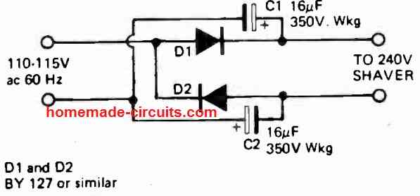
The above shown simple rectifier voltage doubler enables converting your 110V AC to 220 V DC at low current so that you can operate electrical appliances like heaters, soldering iron, electric shavers, mobile chargers etc through this circuit.
Because the output voltage is 220V dc the particular circuit can be only employed to operate little ac/dc motor or heater based equipment, or mobile chargers. It should not be utilized, for instance, to operate electronic items like radio sets, TV sets except if these are specifically ac/dc operated types.

Questions & Answers
After reading your post above, I am to understand it is possible to get 310 volts dc from 120 volts ac single phase. I know little about electronics, that is why I questioned the manufacturer of a milling machine i bought that failed after very little, light use. Trouble shooting points to a bad circuit board. This machine is rated at 2 HP using a DC brushless motor. 120 single phase AC comes in to panel to a contactor, to a circuit board, then to motor. Contactor states on label the motor would be 2 HP with 240 AC feed in, and 1/2 HP with 120 AC feed in. Manufacturer says too light of a contactor was put in, reason for failure of circuit board. They say they use a different circuit board depending on volts input, 220 or 240, but either way the board is feeding the DC brushless motor 310 volts DC, so motor is 2 HP regardless of 120 or 240. FYI, I tested the contactor and it tests ok, there is power going into circuit board, but none going out to motor, bad CB. Does it make sense to you that by installing a higher rated contactor, and CB used with 120 will supply the same DC volts as a 240 feed? And if so, do you believe the HP rating would be the same? And if so, would the 120 feed provide the equal 310 DC volts over continual use (time duration) example motor under load surface milling for a half hour. Also, is there a way to test the motors output, even if I have to ask an electrician for help doing so, I’m curious. Mainly because this DC brushless is not much bigger than a roll of toilet paper, and no nameplate, or any specs on it at all. I greatly appreciate shedding some light on this, thank you, Tom Latimer
The circuit explained in the above post cannot be used for heavy loads or AC inductive loads. It can be only used for low current resistive loads.
Contactors are simply ON/OFF switches which must be rated at minimum two times the load current, otherwise the contacts may corrode or burn due to overload. A contactor will produce the same amount of voltage and current which is being fed to it. I am not sure about your CB, or how it is designed to work? So I cannot say much about it.
A BLDC motor will normally have 3 wires and will require a BLDC driver circuit. If your motor is a two wire motor then it is not a BLDC motor.
Thank you very much, it’s very appreciated to have a chat with you.
My pleasure!
I Don’t think so because the input is 120 volts and the output is 12 vac the florescents sound 20 watts Thank you anyway for answering me it’s very appreciated I’m looking for a solution to make the fluorescent bulbs work if you have a solution please let me know
No problem, hope you are able to solve it soon….presently I do not seem to have an appropriate circuit for this, If I get a solution will update it here for you!
thank you mrs are we able to operate a 220 volt electronic ballast buy in Chinese stores being my network which is 120 volt
Yes you can, according to me. But along with the ballast the fluorescent tube must be also rated at 220 V AC.
the welding inverter circuit needs a 310v input, this circuit supplies 300vdc, the network here is 110v so I need to raise the voltage to this point so that the inverter welding machines can work …. can you help me ???
Hello Wesly. If your welding device is for micro=jeverly weldworks – it have around 100-200watt power – the Mr.Swagatam’s circuit might be useful with appropriated rise of both 47mkFarade capacitors to 800-1500mkF for 100-150W weldingmachine. Also must be changed diodes 2N4007 to a 20-25 ampere’s. And the opto-triac BRT12 mist be changed to a 25-35Amp with a correct thermal sink.
If your erlding machine’s power around 600-1000W – try to use a simplest voltage amplifier – it consist of 2 consiquent capacitors (C#1 and C#2) and of 2 diodes – ‘gold classic’. These diodes must be 100-140Amp of 50milisecond@spike current with more than 400V back woltage. Everyone of capacitors shell be 10000-25000microfarades for a 1 kilowatt of welding machine – just step by step add a 3000-6000 mikrofarade cpacitors until enough exit ontained – must be aldays C#1 = C#2!!! D#1 and D2 can be different – only total amount of D#1 and D#2 shell be equal. But the way is not cheap in money – it is good if you are a source of old but workable AND RELIABLE elements – all old elements are high risc of fire and of electric shok!!!!!!!
For welding machines around 700-3000watt the best way is a transformer – as recommended by the Mr.Swagatam.
The above circuit cannot be used for welding purpose since it is low current device. You will have to use a transformer for the step-up