This adjustable power supply is capable of delivering a maximum output of 12 A with an adjustable voltage from 4 V to 20 V through many LM317 ICs connected in parallel. It will allow testing of any device requiring a significant power supply, such as a direct current motor, a car amplifier, or even a transceiver station. The potential applications are numerous. Its features are as given below:
- Adjustable voltage between approximately 4 V and over 20 V, depending on the adopted transformer.
- Output current of 12 A.
- Built-in current limitation for the parallel LM317 regulators.
- Built-in thermal protection for the parallel LM317 regulators.
Furthermore, the current, limited to 12 A in this version, can be significantly increased by adding additional LM317 regulators in parallel.
In such cases, the transformer should be more powerful (the amperage it can provide should be approximately 30% higher than the desired output power; for example, for 15A available at the output, the transformer should be able to provide around 18 A).
We will leave it to our readers who wish to proceed with this power increase to take care of designing another printed circuit.
Circuit Description
The LM317, an integrated regulator, is quite an old and widely used integrated circuit that you practically encounter in every setup requiring a precisely adjustable power supply.
It is a three-legged voltage regulator capable of handling a differential voltage between input and output of up to 40V. It can provide a minimum current of 1.5A and features current limitation and thermal protection.
Its line regulation is 0.01%, and its load regulation is 0.1%. Implementing it requires only two external resistors to adjust the voltage (apart from rectification and filtering capacitors).
It possesses all the qualities that make it a robust and versatile regulator.
The 12 A power supply's general schematic principle is represented in the figure below, taken from the manufacturer's application note.
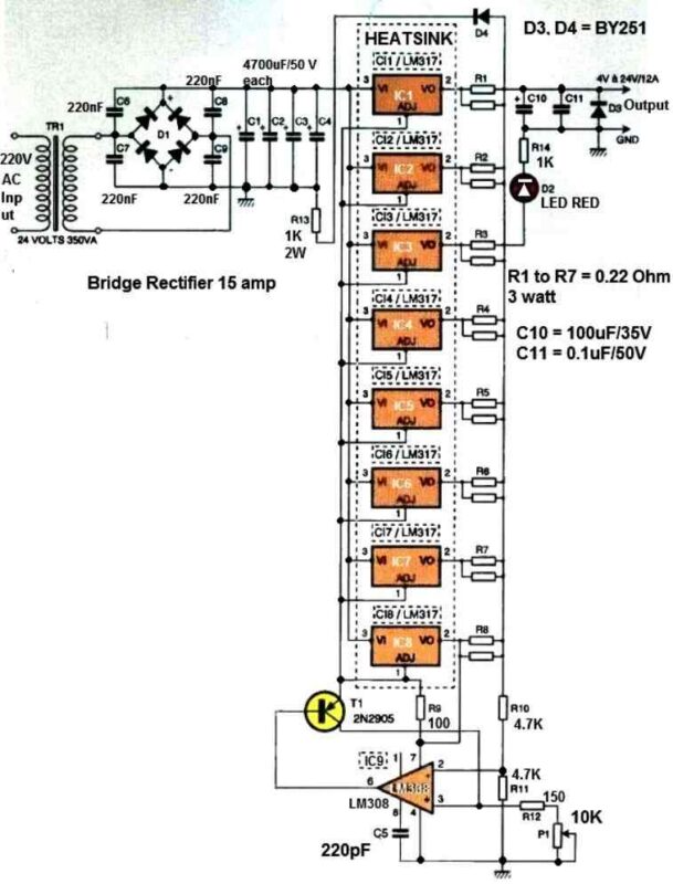
Starting from the left side of the schematic, we find the bipolar switch for turning the mains circuit on and off. A 4A fast fuse protects the entire power supply.
The mains filter interposed in the power lines is not obligatory but desirable as it attenuates the parasites carried by the 220V and voltage spikes.
This type of filter is commercially available and easy to use since it has connection pins that need to be connected.
Next come the transformer and the rectifier with its four 220nF capacitors. Filtering is ensured by four 4,700μF capacitors with a rated voltage of 50V, providing sufficient safety margin.
With the given capacitance values, this results in approximately 2,500μF per ampere. This value should be considered if the power supply's output current is increased by adding additional regulators, as mentioned earlier in the article.
Resistance R13 accelerates the discharge of capacitors C1 to C4 when the power supply is turned off. Diode D4 shunts the regulation system to protect it when the power supply is connected to a capacitive load or used as a battery charger.
The regulation device consists of eight LM317 regulators, integrated circuit IC9, transistor T1, resistors R10 to R12, and potentiometer P1.
Each LM317 regulator delivers the required current through the low-value power resistors R1 to R8, intended to balance the current supplied by each LM317 (none of them should supply precisely the same current).
Principle of adjusting the output voltage
The principle of adjusting the output voltage of all the parallel connected LM317 ICs is shown in the following figure. The LM317 provides a constant reference voltage of 1.25 V on its adjustment pin, which is also present across the 100-ohm resistor.
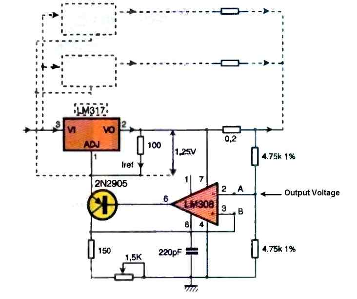
The output voltage depends on the ratio between this resistor and the one connecting the adjustment pin to ground. If its value is zero, the output voltage equals 1.25V.
If this value increases, the adjustment pin is no longer at ground potential, and the output voltage increases. The transistor acts as an adjustable resistor controlled by the operational amplifier.
The operational amplifier's inverting input receives the output voltage feedback, derived from the voltage divider formed by the two 4.75K ohm resistors.
As an operational amplifier tries to make both its inputs at the same potential, it will command the transistor to maintain its non-inverting input at the same voltage as its inverting input.
This is achieved by adjusting the voltage on the regulator's adjustment pin, leading to a change in the output voltage.
By manipulating the potentiometer P1, if the voltage at point A (input+) is decreased by moving the cursor toward ground, the operational amplifier makes the transistor more conductive.
The potential on the adjustment pin decreases, and the output voltage also decreases, equalizing the potential at point B.
Conversely, increasing the voltage at point A makes the transistor less conductive, and the adjustment pin receives a higher voltage. The output voltage also increases, and point B is again at the same potential as point A.
Through this process, it is impossible to simply bring the output voltage to 0 V. However, we believe that this will not be a hindrance to the utilization of such a power supply.
Construction
We insisted that the entire system be integrated onto the same printed circuit board, which avoids the need for wiring connections, which are always long and tedious to perform.
That's why the board has respectable dimensions, approximately 200mm by 150mm.
The design of the printed circuit (shown below) is very precise and easily reproducible.
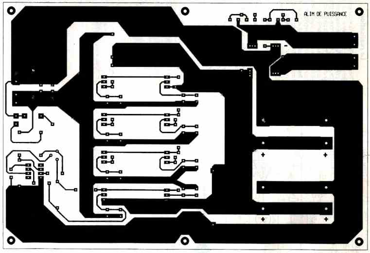
As can be seen in the photograph at the beginning of the article, most of the available space is occupied by the parallel LM317 on heat sinks and the capacitors.
The implementation will, of course, start with the realization of the printed circuit board, followed by drilling and etching, which will protect the copper from oxidation and give the whole assembly a very aesthetic appearance.
The drawing representing the component layout is shown in the figure below.
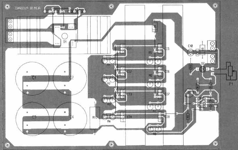
The wiring will begin with the placement of all the straps, which would be impossible to do after mounting the heat sinks.
Then, all the smaller components will be soldered: resistors, capacitors (double-check their polarities before soldering), integrated circuits (ICs), and transistors.
The power resistors R1 to R8 should have a value between 0.16 ohms and 0.22 ohms. If you find the right value (e.g., 0.18 ohms or 0.22 ohms), each resistor will be unique. Unfortunately, we only had resistors with a value of 0.33 ohms.
That's why the printed circuit board is designed to allow parallel connection of two resistors, which seemed more appropriate since these values were not readily available. The power they should be able to dissipate is at least 3W.
Before soldering the regulators, they should be positioned and fixed to their heat sinks. Insulators made of mica and plastic canons for screw holes (if nylon screws are used, the plastic canons become unnecessary) should be used.
Silicone grease should also be applied to both sides of the mica insulator to ensure good heat dissipation from the regulators. Once done, the heat sinks will be placed and fixed with screws, and the regulator pins will be soldered.
The bridge rectifier will be screwed onto its heat sink, with grease applied as well. The recommended bridge rectifier in the parts list requires a minor modification.
Its connection pins are intended to be linked with special connectors (flat, automotive-style). It will be necessary to use a good pair of cutters to reduce the width of the pins so that they can be inserted into the holes provided on the printed circuit board and soldered.
The connection of the printed circuit board to the transformer, as well as the output terminals of the power supply, will be done using screw terminals.
These terminals are doubled due to the current they will carry. LED D2 will be connected using wires, as well as the two terminals of potentiometer P1, so they can be mounted on the front face of the power supply.
The same applies to fuse F1, which will be a model screwed onto the back of the enclosure. A neon light can be added to indicate the presence of mains voltage.
If a mains filter is used, it will be placed inside the power supply enclosure. All connections carrying 220 V voltage will be insulated using heat-shrinkable tubing.
Final Assembly
Once the wiring is completed, take a few minutes to verify the soldering, especially at the parallel connected LM317 solder joints. Then, connect the assembly to the transformer.
The connecting wires should be of a large diameter to handle the significant current required.
After powering on, ensure that adjusting the potentiometer in both directions results in a decrease or increase in the output voltage.
Now, connect a load to the power supply, which can be two 12V automotive bulbs connected in series, with a total power of 50W.
Connect an ammeter to check the current flow and a voltmeter across the power supply to ensure the voltage remains constant.
With this load configuration, the consumption should be around 4A, which is approximately one-third of what the circuit can provide.
Another test can be performed by doubling or tripling the load. If this power supply were to be used at its maximum current capacity, consider providing additional cooling with a fan.
A suitable fan can be easily found at computer component retailers and at an affordable price. A thermostatically controlled model with a sensor can be preferred to avoid constant fan noise.
Now, you have a robust power supply ready to serve various purposes. We believe that readers who embark on this project will not regret the effort they put into it.


Comments
Hello sir Swagatam thanks for your quick response… So, it should be a power supply with digital potentiometer?
Hi Carlos, which circuit are you referring to??
Hello good afternoon, my name is Carlos, I want to know if you have a circuit for a variable power supply from 0 to 25 or 30vdc. But every time it is turned on, it starts at 0v. Thank you very much in advance.
Hello Carlos,
I have that circuit but using a potentiometer to adjust the voltage, and using a potentiometer it is impossible to make it start from zero volts, so it doesn’t look a feasible idea to me.