• Skip to main content
  • Skip to primary sidebar

Homemade Circuit Projects

Need circuit help? Post them in the comments! I've answered over 50,000!

Blog | Categories | About | Contact | Calculators-online
You are here: Home / Datasheets and Components / IC 4018 Datasheet, Pinout Function Explained

IC 4018 Datasheet, Pinout Function Explained

Last Updated on February 24, 2023 by Swagatam Leave a Comment

IC 4018 is a 16-pin CMOS presettable divide-by-N counter, also known as a binary counter. It is commonly used in digital electronics for frequency division and timing applications.

Table of Contents
  • Description
  • Features:
  • Pinout Description
  • Applications:

Description

The IC 4018 family includes 5 Johnson-Counter stages, buffered Q outputs from each stage, and counter preset control gating. There are CLOCK, RESET, DATA, PRESET ENABLE, and 5 separate JAM inputs.

Divide by 10, 8, 6, 4, or 2 counter combinations could be achieved by supplying the Q5, Q4, Q3, Q2, Q1 signals back to the DATA input, in that order.

By using a CD4011B to gate the feedback connection to the DATA input, you may build divide-by-9, 7, 5, or 3 counter arrangements. Several CD4018BMS units could be used to create divide-by functions bigger than ten.

During the positive clock-signal transition, the counter advances one count. On the clock line, Schmitt Trigger action allows for infinite clock rise and fall times.

A high RESET signal resets the counter to an all-zero state. A high PRESET-ENABLE signal permits data from the JAM inputs to be used to preset the counter. To ensure the right counting sequence, anti-lock gating is given.

Features:

  • Supply voltage range: 3V to 18V
  • Low power consumption: typically 10µA at 5V
  • Operating temperature range: -55°C to +125°C
  • High noise immunity: 0.45Vdd typ.
  • Schmitt-trigger input circuitry for noise immunity
  • Output capability: standard and high-speed (TC output)
  • Pin-compatible with other 4000-series CMOS devices

Pinout Description

The pinout details of the IC 4018 can be seen in the following figure:

4018 IC datasheet

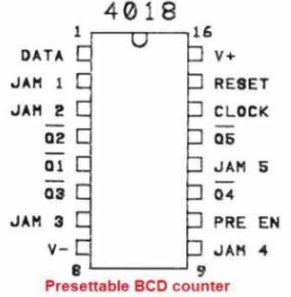
The IC 4018 is a 4-bit binary counter with a maximum count of 16 (2^4). It can be preset to any value between 0 and 15 using the four preset inputs (Q1-Q4).

The clock input is used to advance the counter by one count on the rising edge of each clock pulse. The clock enable input (Pre EN) and output enable input (OE) are used to enable or disable the clock and output signals, respectively.

The master reset input (MR) is used to clear the counter to zero when pulled low. The carry output (TC) goes high when the counter reaches its maximum count, and can be used to cascade multiple counters for higher counting capability.

Applications:

  • Frequency division and timing circuits
  • Digital clocks and timers
  • Industrial control systems
  • Measurement and instrumentation systems
  • Counting and sequencing circuits

You'll also like:

  • 1.  INA219 Current Sensor Circuit Diagram and Datasheet
  • 2.  500V, 20A MOSFET IRFP460 Datasheet, Pinouts
  • 3.  IC 4016 Datasheet, Pinout Function
  • 4.  Half-Bridge Mosfet Driver IC IRS2153(1)D Datasheet
  • 5.  BEL188 Transistor – Specification and Datasheet
  • 6.  2N3904 Datasheet [40V, 200 mA NPN Transistor]

About Swagatam

I am an electronics engineer with over 15 years of hands-on experience. I am passionate about inventing, designing electronic circuits and PCBs, and helping hobbyists bring their projects to life. That is why I founded homemade-circuits.com, a website where I share innovative circuit ideas and tutorials. Have a circuit related question? Leave a comment.... I guarantee a reply!

Previous Post: « IC 4016 Datasheet, Pinout Function
Next Post: IC 4020 Datasheet, Pinout Functioning Explained »

Reader Interactions

Need Help? Please Leave a Comment! We value your input—Kindly keep it relevant to the above topic! Cancel reply

Your email address will not be published. Required fields are marked *

Primary Sidebar


Subscribe to New Circuits

Categories

  • Arduino Projects (87)
  • Audio and Amplifier Projects (132)
  • Automation Projects (17)
  • Automobile Electronics (101)
  • Battery Charger Circuits (83)
  • Datasheets and Components (104)
  • Electronics Theory (143)
  • Free Energy (37)
  • Games and Sports Projects (11)
  • Grid and 3-Phase (19)
  • Health related Projects (25)
  • Home Electrical Circuits (12)
  • Indicator Circuits (14)
  • Inverter Circuits (87)
  • Lamps and Lights (142)
  • Meters and Testers (69)
  • Mini Projects (46)
  • Motor Controller (64)
  • Oscillator Circuits (27)
  • Pets and Pests (15)
  • Power Supply Circuits (108)
  • Remote Control Circuits (50)
  • Security and Alarm (64)
  • Sensors and Detectors (101)
  • Solar Controller Circuits (59)
  • Temperature Controllers (42)
  • Timer and Delay Relay (49)
  • Transmitter Circuits (29)
  • Voltage Control and Protection (37)
  • Water Controller (36)


  • Privacy Policy
  • Cookie Policy
  • Disclaimer
  • Copyright
  • Videos
  • Sitemap


People also Search

555 Circuits | 741 Circuits | LM324 Circuits | LM338 Circuits | 4017 Circuits | Ultrasonic Projects | SMPS Projects | Christmas Projects | MOSFETs | Radio Circuits | Laser Circuits | PIR Projects |

Social Profiles

  • Twitter
  • YouTube
  • Instagram
  • Pinterest
  • My Facebook-Page
  • Quora
  • Stack Exchange
  • Linkedin


  • © 2025 · Swagatam Innovations