This IC 4060 calculator lets you type R1, R2, and C, and see what frequency IC 4060 will give at each output pin. It is super useful if you want to make timers, blinkers, clocks, flasher or any time delay circuit.
How this 4060 Calculator Works
Takes input values for:
- Timing Resistor (R1 + R2)
- Timing Capacitor (C)
Then it Calculates:
- Oscillator frequency
- All 4060 output frequencies (Q4 to Q14)
As per the 4060 internal oscillator formula:
f = 1 / (2.3 × Rt × Ct)Where:
Rt= total timing resistance (R1 + R2) in ohms.Ct= timing capacitor in farads.f= base frequency (at pin 7, fed to internal binary counter).- Each output divides fosc by a binary power (Q4 = fosc ÷ 16, Q5 = ÷32, ..., Q14 = ÷16384).
Example:
If suppose we have:
- R1 = 10k
- R2 = 10k
- C = 0.1 µF
Then we may get the following results from the calcuulator:
- fosc ≈ 217.39 Hz
- Q4 = ~13.59 Hz
- Q14 = ~0.0133 Hz (1 pulse every 75 seconds)
IC 4060 Frequency & Time Delay Calculator
How This IC 4060 Calculator Works
here we are using IC 4060, right... that chip has an inbuilt oscillator and a 14-stage binary counter inside. That means it first makes a frequency using an RC network (resistor + capacitor), then it divides that base frequency through a chain of flip-flops and gives it on different output pins.
First, It Needs 3 Timing Parts:
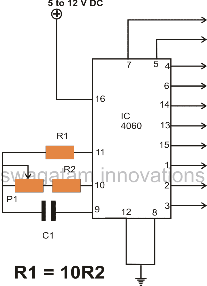
- R1 = Resistor connected between pin 10 and pin 9
- R2 = Resistor between pin 10 and pin 11
- C = Capacitor between pin 9 and ground
We can say that this forms the oscillator tank circuit for the IC. That now sets how fast it pulses internally.
How to Find the Oscillator Frequency:
We use this formula:
f = 1 / (2.3 × Rt × Ct)Where:
- Rt = R1 + R2 (total resistance in ohms)
- Ct = C in farads
- 2.3 is just a constant that comes from internal logic timing in 4060
So this frequency is made at pin 7, but we do not use it directly, instead it goes inside the IC to the flip-flop counter.
Then What Happens?
The IC then divides that base frequency step by step by 2 every time (like digital binary):
- Q4 → divide by 16
- Q5 → divide by 32
- Q6 → divide by 64
- Q7 → divide by 128
- and so on...
That is how we get slower and slower frequencies at each output pin. IC 4060 gives these outputs from Q4 to Q14 so 11 stages in total.
Example Case
Let’s say:
- R1 = 10k
- R2 = 10k
- C = 0.1 µF
Then:
- Rt = 20k
- Ct = 0.1 µF = 0.1 × 10⁻⁶ = 1e-7 F
- f = 1 / (2.3 × 20000 × 1e-7) ≈ 217 Hz
So now inside IC this 217 Hz goes in and gets divided.
You will get:
- Q4 = 217 / 16 = 13.5 Hz
- Q5 = 217 / 32 = 6.8 Hz
- Q14 = 217 / 16384 = 0.0132 Hz → that's like 1 pulse every 75 seconds
So friends now you can see, higher the capacitor or higher the resistance → then lower the frequency.
Need Help? Please Leave a Comment! We value your input—Kindly keep it relevant to the above topic!