• Skip to main content
  • Skip to primary sidebar

Homemade Circuit Projects

Need circuit help? Post them in the comments! I've answered over 50,000!

Blog | Categories | About | Contact | Calculators-online
You are here: Home / Inverter LC Filter Calculator

Inverter LC Filter Calculator

Let’s say we have a push-pull or full bridge inverter and its output goes to the primary of a transformer, and the secondary gives you high voltage AC like 220V square wave.

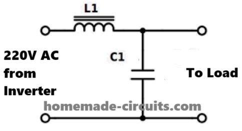
Now to make this AC waveform smooth and more like a sine wave we connect an LC low-pass filter just after this secondary, like this:

Connections Details of the LC Filter:
inverter LC filter
  • Take the two output wires from the transformer secondary — this is your 220V AC (square wave).
  • Now we connect a series inductor (L) in one of the wires — just one wire, like in series, not both wires.
  • Then after the inductor, we put a high voltage capacitor (C) across the output, like between the two wires, that is parallel to the load.

Now to caalculate the values of the L and C, you can use the following calculator:

Calculator by homemade-circuits.com

Inverter Output LC Filter Calculator


How to Decide this fc Value?

We do not want to block 50Hz because that is our main signal. We want to block the switching frequency harmonics like:

  • 300Hz
  • 600Hz
  • 1kHz
  • And higher junk frequencies

So we choose fc just above 50Hz but much below the unwanted high frequencies.

Rule of Thumb:

You can select cut-off (fc) between:

3 × main frequency......... upto 10 × main frequency

Example:

If your inverter PWM has big amount of noise like around 1kHz to 3kHz, then you pick fc = 300Hz, so that:

  • 50Hz passes cleanly.
  • Above 300Hz (like 1kHz, 2kHz) get blocked fast.
  • Gives smooth sine output.

Final Tip:

So just take 5 or 6 times the 50Hz, then:

fc ≈ 50 × 6 = 300Hz

It is a safe and effective choice for LC filter to clean inverter waveform.

Reader Interactions

Need Help? Please Leave a Comment! We value your input—Kindly keep it relevant to the above topic! Cancel reply

Your email address will not be published. Required fields are marked *

Primary Sidebar

circuit simulator image

Subscribe to New Posts


Categories

  • Arduino Projects (89)
  • Audio and Amplifier Projects (132)
  • Automation Projects (17)
  • Automobile Electronics (101)
  • Battery Charger Circuits (83)
  • Datasheets and Components (104)
  • Electronics Theory (143)
  • Free Energy (37)
  • Games and Sports Projects (11)
  • Grid and 3-Phase (19)
  • Health related Projects (25)
  • Home Electrical Circuits (12)
  • Indicator Circuits (14)
  • Inverter Circuits (88)
  • Lamps and Lights (142)
  • Meters and Testers (69)
  • Mini Projects (46)
  • Motor Controller (64)
  • Oscillator Circuits (27)
  • Pets and Pests (15)
  • Power Supply Circuits (108)
  • Remote Control Circuits (50)
  • Security and Alarm (64)
  • Sensors and Detectors (101)
  • Solar Controller Circuits (59)
  • Temperature Controllers (42)
  • Timer and Delay Relay (49)
  • Transmitter Circuits (29)
  • Voltage Control and Protection (39)
  • Water Controller (36)


Other Links

  • Privacy Policy
  • Cookie Policy
  • Disclaimer
  • Copyright
  • Videos
  • Sitemap


People also Search

555 Circuits | 741 Circuits | LM324 Circuits | LM338 Circuits | 4017 Circuits | Ultrasonic Projects | SMPS Projects | Christmas Projects | MOSFETs | Radio Circuits | Laser Circuits | PIR Projects |

Social Profiles

  • Twitter
  • YouTube
  • Instagram
  • Pinterest
  • My Facebook-Page
  • Quora
  • Stack Exchange
  • Linkedin


  • Recent Comments

    • Swagatam on How Shunt Regulator TL431 Works, Datasheet, Application
    • SA on How Shunt Regulator TL431 Works, Datasheet, Application
    • Farmtech on Free Energy Generator Circuit – The N-Machine
    • Nitesh Agrawal on How to Design Simple LED Driver Circuits
    • Swagatam on How to Design Simple LED Driver Circuits

    © 2025 · Swagatam Innovations