This XL3608 2A mini DC to DC Boost Converter module is super compact and efficient and it is just perfect for powering all sorts of devices and systems. Let's learn about its main features in greater details:
Main Features:
Input Voltage Range: We can feed this module with an input voltage ranging from DC 2.5-11.5V. But remember, it needs to be at least 0.5V lower than the output voltage we are aiming for.
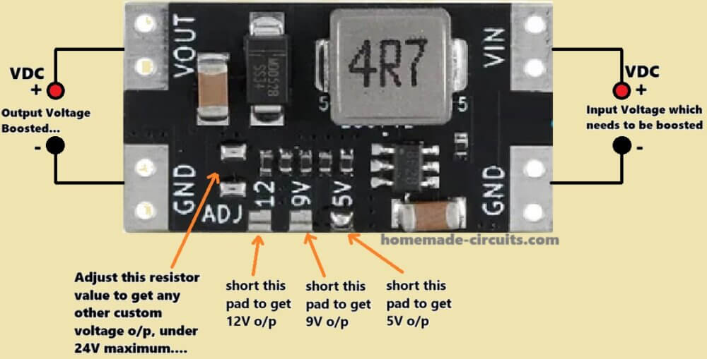
Output Voltage Options: It gives us fixed output voltages of 5V, 9V, and 12V, and if we want something custom, then we can adjust the output voltage using an ADJ path by soldering in some resistors.
Maximum Input Current: The module can handle a maximum input current of 2A.
Output Current: Now the output current depends on the input voltage and current, so we cannot just expect to get 2A at those specified voltages without considering the input limitations.
Efficiency: This module is a real energy-saver boasting a high conversion efficiency of up to 94%.
Switching Frequency: It operates at a switching frequency of about 1.2MHz.
Operating Modes: It works in both PWM (Pulse Width Modulation) and PFM (Pulse Frequency Modulation) modes. When the load current increases then it automatically switches from PFM to PWM to optimize efficiency and reduce static noise.
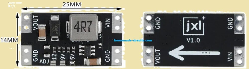
Module Size: It is super compact measuring 24.4x13.7mm making it perfect for small applications.
Interface: It uses solder pads that are compatible with 2.54mm rows of pins so connecting it is a breeze.
Technical Specifications:
- Module Type: Switching Power Supply, Boost Power Supply
- Input Voltage: DC 2.5-11.5V
- Input Current: 2A (max)
- Output Voltage: DC 5V, 9V, 12V
- Output Power: Input Voltage x 1.5 (max)
- Switching Frequency: Approximately 1.2MHz
- Working Mode: PWM/PFM
- Quiescent Current: 200uA-600uA (PFM mode)
- Setting Method: Jumper Pad Selection, ADJ Pad Adjustable
- Module Interface: Solder Pad
- Module Size: 24.4x13.7mm
Overall the XL3608 is a super versatile and efficient boost converter that is perfect for any project where we need a compact, reliable step-up power solution.
Connection Details
Connect the IN+ (Positive Input) to the positive terminal of your power source (e.g. a battery).
Connect the IN- (Negative Input) to the negative terminal of your power source (e.g. the negative terminal of a battery).
Connect the OUT+ (Positive Output) to the positive terminal of the device you want to power.
Connect the OUT- (Negative Output) to the negative terminal of the device you want to power.
How to Set the Output Voltage:
The XL3608 uses jumper pads or an adjustable potentiometer to set the output voltage to 5V 9V or 12V.
You can select the desired voltage by moving the jumper to the appropriate position or adjusting the potentiometer.
Module Interface:
The module uses solder pads which can be connected to 2.54mm rows of pins for easy integration into your circuit.
Powering Up:
Once everything is connected you can apply power to the input terminals. The converter will then start boosting the voltage to the selected output level.
Safety Precautions
Ensure that your input current does not exceed 2A to prevent overheating or damage to the module.
You must always verify the output voltage before connecting it to sensitive devices to avoid any damage to them.
Applications:
We can use the XL3608 module in all sorts of projects that need a stable and efficient boost in voltage like powering small electronic devices, DIY projects, or systems where we need to step up the voltage from a lower input source.
Circuit Diagram
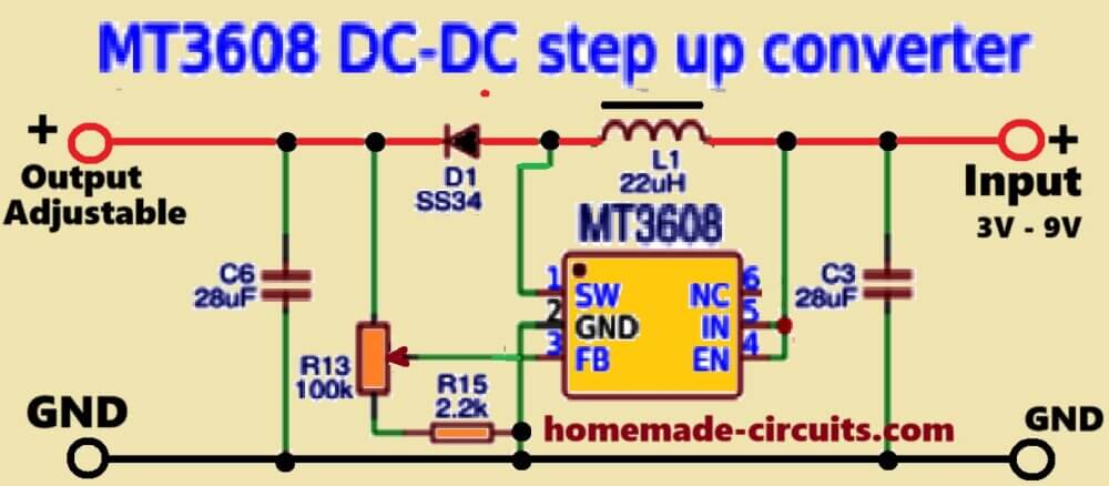
This circuit diagram represents a XL3608 DC-DC step-up (boost) converter circuit diagram using the MT3608 IC. It is used to boost a lower voltage (for example 3V to 9V) to a higher voltage.
Working Principle:
The MT3608 is a high-efficiency step-up (boost) converter IC that uses an inductor-based switching regulator to increase the input voltage.
Component Description:
MT3608 IC = Oscillator IC Pinouts
- Pin 1 (SW): Switch output connected to the inductor (L1).
- Pin 2 (GND): Ground.
- Pin 3 (FB - Feedback): Used for voltage regulation.
- Pin 4 (EN - Enable): Connected to VIN, enabling the IC.
- Pin 5, 6 (IN+): Input voltage.
L1 (22µH boost Inductor)
Stores energy during the switch-on cycle and releases it when the switch is off, boosting the voltage.
D1 (SS34 Schottky Diode)
A fast-recovery diode that prevents reverse current flow and helps maintain efficiency.
Capacitors (C3 & C6 - 20µF each)
Used for input and output voltage filtering to reduce ripple.
Resistors (R13 = 100kΩ, R15 = 2.2kΩ)
Forms a voltage divider network for the feedback pin (FB) to set the output voltage.
Potentiometer (Variable Resistor, R13)
Adjusts the output voltage by changing the feedback resistance.
How it Works
The circuit takes 3V to 9V as the input voltage and then boosts it to a higher adjustable voltage levels.
The inductor L1 stores energy when the switch inside MT3608 turns on.
When the switch turns off, then the stored energy in the inductor is released through D1 causing a boosted voltage at the output.
The capacitors (C3 & C6) work as filter capacitor to smooth the output voltage.
The feedback network (R13, R15, and potentiometer) adjusts the output voltage to the intended levels.
The IC MT3608 automatically regulates the switching cycle frequency to maintain the required output voltage.
Calculations
The output voltage of the IC MT3608 boost converter is given by the formula:
Vout = 0.6V * (1 + R13 / R15)
Where:
Vout = Output voltage
0.6V = Internal reference voltage of MT3608
R13 = Adjustable resistor (100k in the diagram)
R15 = Fixed resistor (2.2k in the diagram)
Example Calculation:
If R13 = 100k and R15 = 2.2k, then:
Vout = 0.6V * (1 + 100k / 2.2k)
Vout = 0.6V * (1 + 45.45)
Vout = 0.6V * 46.45
Vout = 27.87V
By adjusting the resistor R13 you can change the output voltage within the limits of the MT3608 (which is typically a maxx voltage of 28V).


Need Help? Please Leave a Comment! We value your input—Kindly keep it relevant to the above topic!