A practical electronics engineering resource focused on tested circuit projects, clear theory explanations, design calculations and real world troubleshooting support for students, hobbyists, and professionals.
Questions Answered with Practical Working Solutions
Backed by more than two decades of hands on circuit design experience, reader questions posted in the comments are reviewed and answered personally. Wherever necessary, circuit corrections, design improvements, and verified working solutions are provided to ensure accuracy and reliability.
How To Use This Website
- Start with the Electronics Tutorials section if you are new to circuit design.
- Explore application based projects to find ready to use circuits.
- Read the comments for practical tips, corrections, and reader discussions.
- Post your questions to get guidance and improvements where needed.
Learn Electronics Step By Step
Foundational tutorials explaining electronic concepts, calculations, and working principles in a simple and practical way.
Detailed explanations of semiconductor devices and circuit theory with practical examples and applications.

Arduino programming tutorials and microcontroller based automation projects with complete circuit details.
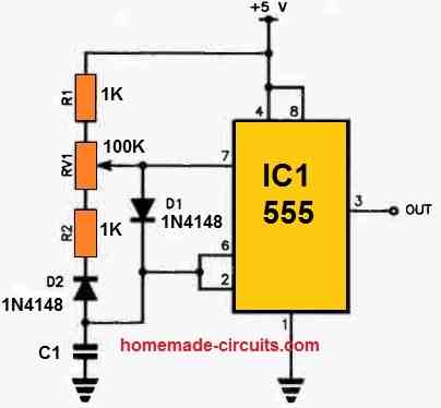
Classic and modern IC 555 timer circuits explained with calculations, diagrams, and application ideas.
Power Electronics and Energy Systems
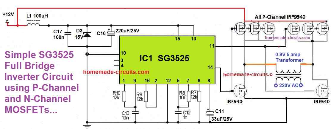
Designs that convert DC power into 220V AC with explanations ranging from basic to advanced sine wave systems.
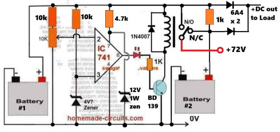
Controlled battery charging circuits covering lead acid, lithium, and industrial battery systems.
Fixed and variable voltage power supply projects for workbench testing and embedded applications.
Solar charge controllers and renewable energy projects using PWM, MPPT, and microcontroller techniques.
Application Based Electronic Projects
Electronic circuits designed to enhance safety, automation, and efficiency in home electrical systems.
Control and automation circuits used in industrial machinery and process systems.
Automotive electronic projects for lighting, safety, and performance enhancements.
Speed and torque control circuits for DC and AC motors used in home and industrial applications.
Decorative and functional LED lighting circuits including dimmers, chasers, and drivers.

Wireless and IR remote control circuits for convenient device operation from a distance.
Specialized and Utility Circuits
Wireless control and GSM based communication projects for monitoring and automation.
Hand-built electronic meters and testers useful for diagnostics and troubleshooting.
Delay timers and relay switching circuits for automation and protection applications.
Learning Through Discussion
A lot of the circuits here slowly get better through questions and discussions in the comments. Readers point out real world problems, ask for small changes, or request clarifications, and over time this back and forth helps turn the designs into more reliable and practical working circuits.
Try and Test Circuits Online
To help readers better understand how circuits behave, this website also includes a simple online circuit simulator. It can be used to visualize basic circuit operation, test component changes and explore circuit behavior before building it practically.

Recent Community Discussions
Latest questions, answers, and circuit improvements discussed by readers and the author.
Hi Sagar, I can recommend you the wifi detector circuit, which uses two opamps in series. To make it super…
Hi Swagatam, Sorry for the repeated comment- there was a glitch, and the previous one wasn’t showing up. Here are…
Hi King, You can try the following circuit, it won't chatter: https://www.homemade-circuits.com/wp-content/uploads/2026/03/low-battery-latch-circuit.jpg You replace the opamp with any other standard…
Hi Sagar, I have already answered to your comment. I hope you are getting the email notifications. You can also…
Hi Swagatam, We attempted to build one of your op-amp circuits, but unfortunately, it is not working on our end.…
Common Problems Addressed
- Circuits that do not work as expected after assembly.
- Confusion about component values and calculations.
- Improper power supply or overload issues.
- Noise, heating, and instability in practical circuits.
- Modification of existing circuits for custom requirements.
Note: All circuits are provided for educational and experimental purposes. Readers are advised to follow proper safety precautions while working with mains voltage and high power circuits.
Comments
Hello, would you please can you share the circuit diagram of XL6009 DC to DC step up. and the PCB layer design> Thanks”
You can check out this link:
https://www.haoyuelectronics.com/Attachment/XL6009/XL6009-DC-DC-Converter-Datasheet.pdf
Hi Swagatam
TL;DR
For my motorbike, I would need a circuit that pilot a LED stripe (so, one output with + and -) with two different currents, the lower one by “default” and the higher one only when a positive input goes high. The circuit should be “immune” to the environment, as the outputs aren’t protected from rain.
Long explanation
My motorcycle has a GIVI case mounted on the back, with LED stop lights made by me.
The case has a 2-pins “touch connector” that, when mounted to the bike, touches a “2-plates” connector mounted on the support. Right now the connector is wired to the bike stop light, and i’ve mounted a cheap chinese buck converter in the case just to regulate the current for the LEDs, to avoid overheating problems.
I would like to use the case lights also for running lights, by reducing the current for the LED (i mean: the same LEDs will have a lesser current for running light, and a higher current when the Stop light are needed).
Given that there’s only two pins available between the bike and the case, i think that the only solution is to move the current regulation in the bike, so a LED driver circuit that is powered by the bike rear light, and that takes the Stop lights as input.
The case is removable, and when it is removed the contacts on the support are exposed: when it rains, they can become wet, so the circuit has to able to handle this.
(an image of the GiVi connector: https://imgur.com/E6DeI4H )
Hi Parduz,
The current consumption is decided by the load, so in your case if the voltages for the load operations are not changing then there’s no need to change the current.
If you could show me the schematic then I could understand the situation better and give my suggestions accordingly…
Here’s one article which shows how the same group of LEDs can be used for brake light as well as running turn light indicator:
https://www.homemade-circuits.com/how-to-make-car-led-chasing-tail-light/
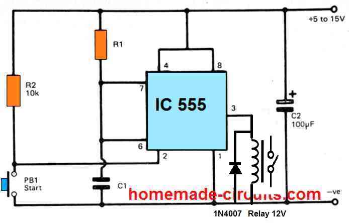
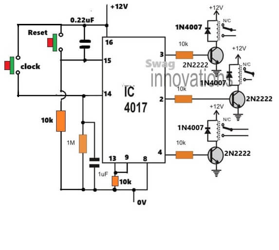
“Did you connect the relay drivers across all the 8 outputs as required by your application? And what is the frequency of the 555 output pulses. Please connect an LED between pin#3 and ground of the 555 IC and make sure the blinks at the rate of 1 pulse per second, and then check the response. Also, if you remove the 555 from pin#14 of the 4017 IC and press the reset button, then pin#3 of 4017 must be permanently ON….please confirm these aspects and let me know… ”
All 8 outputs are connected. The pulse frequency is about 10 pulses per second at its slowest, I do not have a scope. I replaced the pot with a 200K-2M pot and that slowed the pulse to about 5 per second. In both cases, IC 4017 Pin 3 is driving the relay and pin 2 is steady on with a little dimming at the frequency, driving the relay? nothing past that. Removing the 555 from pin 14 and press the reset does make pin 3 steady ON.
10 Hz is too fast to check the response.
Please make it 1 pulse per second, or 1 pulse per 2 seconds, and then check the response. You can do this quickly by replacing the timing capacitor of your 555 IC with some higher value capacitor…
Or you can remove the 555 stage temporarily and replace the pin#14 of 4017 IC with a push button, as shown below:
And please use the REPlY button to reply under the same thread, so that it becomes easy to track the comments for all of us.
Is using your 16 LED Reverse/Forward Chaser Circuit the best way to have 12 outputs, modifying it to trip relays in only one direction for only one sequence like the 8 output circuit you designed for me above? I tried doing it with your 18 LED light chaser circuit using two IC 4017 but it just locks on one one output from the 555 and pin 3 of the first 4017. Your Youtube video on the dual 4017 is really blurry so it is hard to tell if I missed something.
The 16 LED and the 18 LED chaser both will work, if you build it initially exactly as described in the article….the video may be blurry but it proves the working of the design, so you can use it without doubts.
However latching it after the predefined output may require some thinking…
so I’m designing a led sign that says REMEMBER SMILE
the word remember is made up of 31 red leds for the first R then E with 43 yellow M is blue with 33 leds then E with 36 green leds then another blue M with 33 then yellow E with 42 B has 24 blue and18 blue leds the last R is made up of 24 red with 7 yellow leds
the word smile is made up of clear cool white and frosted cool white leds
I’ve done a series of 5 leds for the colors red and yellow and 3 in series for the blue green and white leds.
I’m using a Moffett trigger switch with a push button to manually blink the word remember then another push button and Moffett trigger for the word smile, so I illuminate the word remember then I switch to the word smile with the possibility to turn both words at the same time just for a few seconds at a time
my power source is a car jump pack ET05 S ZEVZO 1600A model ET05
the resistors that I have are 50x 680r 1w 1%, 100x 430r 1/4 watt 1% and 100x 560r 1/4 1% also a verity pack of risistors 1/4 watt 1% risistors also i want to put a 500ohm pot in series to control the overall brightness
I’m holding the sign myself at night alongside of the road panhandling
I don’t want to run at 20 mah because it will be too bright thus the potentiometer
I’ve also have transistors verity pack that has 2n2222s 2n3904sand 2n3906 s8050 ect.
can you help me with the little details of sign such as current limiting risistors because each letter is a separate circuit and I’m getting confused by the calculations for each color and letter.
Hi, you can use this calculator tool to get the series resistor value for each LED string:
https://www.homemade-circuits.com/led-string-series-resistor-calculator/
For more info regarding how the LED strings needs too be configured, you can refer to the following article
https://www.homemade-circuits.com/how-to-calculate-and-connect-leds-in/
Great projects you have! I would like to use the LED chaser circuit at 12v to trip some 12v relays with the LED’s. The coil voltage on the relays I have is 16.7 mA. What would I need to change to make this work? I’m thinking to start with 24VAC as that is what I have at the location and your one circuit that uses a 12v Zener looks like it would work for me.
Thanks, surely that’s possible…how many relays do you want to operate in sequence??, and do you want the sequence to repeat or just a one time operation…
8 relays and a one time shot would be perfect.
You can try the following diagram…you will need to connect the transistor relay drivers across the following pinout sequence…
3, 2, 4, 7, 10, 1, 5, 6, I have shown for the first 3, please repeat the stages for the remaining pinouts of the IC.
To convert 24V AC to 12V DC, use bridge rectifier, filter capacitor, and 12V voltage regulator stage.
https://www.homemade-circuits.com/wp-content/uploads/2026/01/relay-sequencer.jpg
Thanks a bunch for the help! I’ll get the parts and and give it a shot.
Sure, no problems… for the LED indications, you can put one LED each in series with the 10k resistors at the base of the transistors. And also make sure to put a 1k resistor in series with the “clock” input at pin#14. These clock pulses are responsible for initiating the output sequencing of the relays and these clock pulses could be manually generated through a push-button or automatically through an oscillator IC such as IC 555…..
I’m thinking of using your Knight Rider circuit for the NE555 oscillator and zener power circuit, plus the items you mentioned above. Any changes to adapt it for 24vac?
You will just need to do one thing, convert the 24V DC to 12V DC using a 7812 IC, that’s all. You may need to attach a heatsink on the 7812 IC. If you do not want the heatsink hassle, then you can go for the following buck converter, which will be hugely efficient..
https://www.homemade-circuits.com/adjustable-1-2v-to100v-dc-buck-converter-circuit-using-lm5164/
With the original 500K pot and a 47uf cap I can get the pulse frequency right and it cycles through all 8 outputs and stops just like I needed. . Thanks for your help!
Sounds great!! thanks for updating the results.
I have the circuit wired up with a buck converter for the power and the 555 circuit for the pulses from your Knight Rider post. The output at pin 3 of the 555 is steady and goes through the 1K resistor to pin 14 on the 4017. I get the same pulse nonstop only at pin 2 on the 4017 when the reset pushbutton is open and it powers the relay and LED. No outputs to any other output pins on the 4017. Closing the pushbutton stops the pulsing. What am I missing?
Did you connect the relay drivers across all the 8 outputs as required by your application?
And what is the frequency of the 555 output pulses.
Please connect an LED between pin#3 and ground of the 555 IC and make sure the blinks at the rate of 1 pulse per second, and then check the response.
Also, if you remove the 555 from pin#14 of the 4017 IC and press the reset button, then pin#3 of 4017 must be permanently ON….please confirm these aspects and let me know…
Please, trying to make a regulator for a car alternator, that is attached on a 6.5Hp petrol engine, to be used as generator for olive harvesters. Need to give out different specific voltages with a rotor switch, for different voltage working olive harvesters that are going to work standalone or 2-3 of them together when load does not go over alternator’s power. Alternator is a BorgWarner 13.5V-130A, and I have removed the inside regulator, engine’s rpm are going to be stable at about 2000rpm, and have a pulley 2:1 to rotor, and rotor’s resistance is 2.6Ω. The problem is that the regulator must control rotor’s current so that when the tools ask for more Amps to increase current on rotor. Also the circuit is feeding by a 12V-7Ah small battery. The olive harvester tools do not pull over 20-25 at peak (e.x. if they stack and need more power), and about 8-12A at normal working. I’m going to add some fuses on system for more protection. Thank you.
1. https://drive.google.com/file/d/1Ybk9EdnW45eTbYGuHQscbXkXUhTEkMmm/view?usp=sharing
2. https://drive.google.com/file/d/1KdYRGlZjKNdnYkgm-6gPG48qcRY9OPQH/view?usp=sharing
Thanks for your detailed explanation.
I think you might find the following post useful as it contains a few circuit designs which exactly match your requirement.
https://www.homemade-circuits.com/car-alternator-regulator-circuit/
By the way, your Google drive links are not opening, they are showing “access denied”
hello engeneer..can you advice me or give me the best pcb drawing software and best pcb itching process that i can do my own DIY please,Email Khisabriam5@gmail.com
Hi Brian, there are so many online websites which provide you with a facility for designing your own PCBs, you can easily find them by Googling…
Hello again Swagatam,
Thank you for the help in the last two years I need to end this year knowing you provided me a circuit I am asking for now.
I need a very best circuit to charge my car/vehicle battery when need what is the BEST CIRCUIT you can provide me including the charger should go in to ” TRICKLE ” charge when almost complete. (By the way apart from my work Electronics is my best hobby ever)
Your reply will be respected at your earliest convenience.
Thank you in advance.
Dr.Chris Halgryn.
Thank you Dr.Chris, It’s my pleasure!
According to me the following circuit is the simplest and yet the best design for an automatic battery charging.
You can insert the trickle charging feature just by adding a calculated resistor, maybe a 1k resistor across the emitter/collector of the TP36, that’s all is needed. Let me know if you have any doubts regarding this circuit…
https://www.homemade-circuits.com/wp-content/uploads/2024/08/universal-12V-solar-battery-charger-circuit.jpg
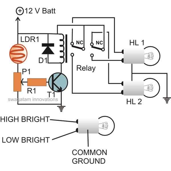
Hi, is this the right place to ask a question about the 6th simple car headlight timer circuit using a 555 chip?
Hi, could you please ask your question under the following article, I will try to solve it as quickly as possible:
https://www.homemade-circuits.com/interesting-timer-circuits-using-ic-555-explored/
Ingenious projects, very inspiring!
Please Boss, I need you to help me with:
1) An inverter circuit with the following specifications:
– Sine wave
– 12v input
– 3kva output
– Short-circuit protection
– Overload protection
– Low battery drainage
– Can power inductor load, e.g heater
2) Explanation on how to increase the output power whenever I need to do so.
Lisborn, for 12V to 3kva inverter design, you will need a 3000/12 = 250 Amp transformer, and a 250 * 5 = 1250 Ah lead acid battery, or a 500 Ah Li-ion battery.
Would you be able to get such huge battery and transformer for this project??
This is quite a big project then.
1) What about 12v to 1000watts inverter with the same functions, including soft start?
2) Could you please suggest the best and cheapest online electronic stores that I can order electronic components from.
Even with 1000 watts, the transformer would need to be 1000/12 = 84 amps.
You can try 48V battery instead, to reduce the current requirement.
Heater may not be an inductive load, unless it is an induction heater, and for a resistive heater a sine wave may not be required.
I think the first circuit from this article will be very much suitable for you:
https://www.homemade-circuits.com/make-this-1kva-1000-watts-pure-sine/
Thanks for the circuit. I love it very well.
1) If I connect my 4 12v batteries in series, it will give me 48v and also power my load, but will it carry the load for the same duration of time with 4 12v batteries of the same capacity connected in parallel?
2) Please help me to suggest online electronic stores that I can order electronic components from.
Thanks, and glad you liked the circuit, hope it works for you…
Yes, the outcome will be even more efficient when connected in series at 48V, but in that case the transformer will also need to be a 48-0-48V transformer…or a 36-0-36V transformer to be precise…
You can get them from any local online store in your country because getting them from international stores away from your country can incur big shipping charges…
Hi Swagatam:
Please discard previous message.
Bear with me as english is not my mother tongue. (machine translated)
I’m new to experimenting with electronics and want to build an electronic version of a simmerstat (https://en.wikipedia.org/wiki/Infinite_switch). My idea is to use the following transistor-based astable multivibrator paired with a solid-state relay ( https://www.homemade-circuits.com/efficient-electronic-relay-ssr-circuit/ ).
https://www.homemade-circuits.com/wp-content/uploads/2025/06/variable-mark-space-ratio-generator-with-waveform-correction-and-sure-start-facility.jpg
Application Context:
This will replace a broken control knob on a single burner electric stove.
The circuit will be housed in a separate heat-resistant enclosure with an outlet to connect the stove.
Key Specifications:
Load: Resistive (2000W)
Mains voltage: 120V
Desired timing: 10-15 second period
Questions:
Interconnection: How should I connect the astable multivibrator to the SSR?
Transformerless Power: Can I use a transformerless power supply for the astable circuit? (Both astable and SSR will share the same mains connection).
Timing: I’d like the astable to have approximately 10-15 second period. How can I adjust component values (resistors/capacitors) to achieve this?
SSR Capacity: Is the linked SSR design suitable for a 2000W/120V (≈16.7A) resistive load? If not, what modifications would you recommend?
Your insights would be invaluable—I frequently visit your electronics site and find your projects exceptionally clear and inspiring. Thank you for sharing your expertise with the community!
Best regards,
Victor Barcaz
Thanks Victor,
I have designed the circuit as per your mentioned specifications, I hope it works for you as intended. However this circuit circuit will not detect the heat from the load and so will not operate like a temperature controlled relay, as we find in electromechanical simmerstats:
https://www.homemade-circuits.com/wp-content/uploads/2025/06/electronic-simmerstat-circuit.jpg
Can only a live circuit be tested with the first circuit?
Which circuit diagram are you referring to?
Gentilissimo Dott. swag
Posseggo un UPS con batteria 12 vl 7A all’acido, quando va via la tensione di rete il suo funzionamento non dura piu’ di un minuto. Vorrei sostituire la batteria con una al litium, ho visto su youtube che una persona sostituisce la batteria con una al litium, ma si puo’ fare? non ci vuole un adattatore ho qual cosa di altro? Gentile Dottor swag Lei cosa ne pensa,la ringrazio anticipatamente.
Hey Tommy, first of all it is important to understand why the problem is happening? Is the battery gone bad, or is the load current too high for the battery? So can you please tell me the load specifications, then I can tell if it is compatible with the battery or not….Yes you can replace your lead acid battery with a Li-ion battery by adjusting full charge cut-off level of the charger.
I would like to make a voltage limiter for my PV array. It occasionally exceeds the inverter/charger limit of 150VDC with 4 panels in series. I can reduce the series strings to 3 panels, but that drops me to 112.5 v and that’s less than ideal. I will be putting a small load by way of some parallel resistors to drop approximately 10 v off, but I would like to be able to get the max voltage during the off peak sunlight times. I’m thinking of something that senses and regulates the voltage to just below the 150 v maximum. The system generates about 34 amps. TIA!
Here’s a simple voltage regulator design you can try. Make sure to upgrade the transistors according to the load current. The zener diode decides the output voltage level. The capacitor can be removed if a slow start is not needed for the load:
https://www.homemade-circuits.com/wp-content/uploads/2020/07/loe-drop-regulator.jpg
Thank you so much. I think this will do the trick.
No problem, please let me know if you face any issues with this circuit.
No problem John,
Yes, the resistor and the VR1 values are ok, and will have no issues for the MOSFET to conduct fully at dusk.
Let’s assume the LDR value at dusk is 1 meg, and the combined value of the resistors is 150k, and the battery voltage is 3.5V, then the MOSFET gate will still receive a gate voltage of around 3V which is enough for the MOSFET to turn ON fully…
If the LED module has a built-in resistor then it should be fine to be used with this circuit…
Hi Swagatam,
Thank you so much for your reply and corrected circuit diagram. Now that you have switched the LDR and resistors around it makes sense. However, I plucked the two resistor values out of the air. I don’t know if they will allow the MOSFET to fully saturate when switched on at dusk.
I know next to nothing about MOSFETS as I was brought up on transistors and limiting the current on the base to avoid damage but I understand MOSFETS are more like a capacitor and are either on or off depending on the drain voltage rather than the current. The specs for the AO3402 are here. Would you be kind enough to check the resistors will allow the MOSFET to fully switch on.
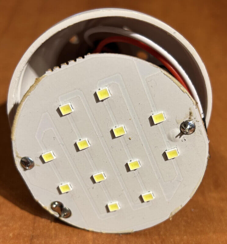
Regarding the LEDs and dropping resistor, I have no information on them and there are no markings (see pics). The dropping resistor is already attached to the board and varies between 4.7 ohm and 5.6 ohm depending on the make of the bulb.
John
Hi John,
Your circuit is almost good, except the LDR/VR1-R2 positions which must be swapped to enable the MOSFET to turn off during daytime.
Here’s the corrected circuit diagram which you can implement:
If you could tell me the specifications of the LED then I can calculate the LED series resistor correctly for you.
https://www.homemade-circuits.com/wp-content/uploads/2025/02/mosfet-LDR-darkness-activated-solar-lamp.jpg