In this post I will try to explain the making of a simple 220 V, 120 V AC mains short circuit breaker using an SCR and a triac combination, (researched and designed by me).
The circuit is an electronic version of the normal main circuit breaker MCB units that we use in our homes.
Note: I did not use a relay for the cut-off, because relay contacts will simply fuse with each other due to heavy current arcing across the contacts during a short circuit condition, and therefore it is highly unreliable.
Why Short Circuit in Homes Can be Hazardous
A short circuit in a house wiring may appear to be something which happens very seldom and folks aren’t too interested to get any relevant precautionary measure installed in their houses and take the hazard very casually.
However once in a while due to some accidental fault, a short circuit in the mains wiring becomes inevitable and it the happening causes a disaster and huge lose.
At times the consequence leads to fire hazards and even lose of life and property.
WARNING - THE PROPOSED CIRCUIT IS NOT ISOLATED FROM MAINS AC, THEREFORE IS EXTREMELY DANGEROUS TO TOUCH IN UNCOVERED POSITION AND WHEN POWERED.
Though many types of short circuit breaker units are available ready made in the market, these are generally very costly.
Moreover an electronic hobbyist will always want to make such an equipment all by him and enjoy its display in the house.
Electronic MCB Circuit Using a Solid State MOSFET SSR
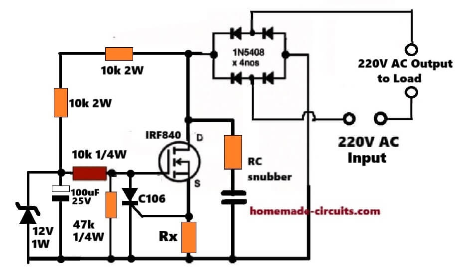
This promising electronic MCB circuit is designed by me, which works as series solid-state electronic circuit breaker for 220V AC mains. It is connected in line with mains, so when it cuts, load is fully disconnected.
Circuit Diagram
How MOSFET And Bridge Rectifier Work
MOSFET together with bridge rectifier behaves like bidirectional solid-state relay. AC input is applied in series with load, and load is connected across 220V AC output terminals. As long as MOSFET remains ON, mains power flows normally to load, nothing blocked.
DC Supply And Normal Operation
Small DC supply is taken from mains using dropper resistors and 12V zener. This DC is only for MOSFET gate bias and sensing circuitry, not for load. Under normal conditions MOSFET gate gets enough voltage, so IRF840 stays fully enhanced. MOSFET stays conductive during both half cycles of AC waveform, therefore load runs normally.
Current Sensing Using Rx
Load current flows through low-value resistor Rx at MOSFET source. During normal operation, voltage across Rx is very small and stays below SCR trigger level. So SCR remains OFF and MOSFET gate bias stays safe.
What Happens During Overload Or Short Circuit
When overload or short circuit happens, then load current rises sharply. Because of this, voltage across Rx also rises. When this voltage crosses SCR gate trigger threshold then SCR fires and latches immediately.
As soon as SCR turns ON, then it pulls MOSFET gate to ground. Gate-source voltage collapses, MOSFET goes into cutoff. Since MOSFET is in series with mains, turning it OFF instantly disconnects load from AC supply.
SCR stays latched even after overload disappears, means that MOSFET remains OFF permanently. So power must be removed briefly to reset circuit and bring it back to its original condition. This gives proper breaker-like behavior and protects mains wiring and load from overheating or damage.
Mathematical Derivation Of Rx
Trip condition depends on SCR gate trigger voltage.
For C106 SCR
Typical gate trigger voltage ≈ 0.6V to 0.8V
Design safely around 0.7V
Basic relation
Trip current = SCR trigger voltage / Rx
Rearranging gives:
Rx = SCR trigger voltage / Trip current
Example Calculations
For 5A trip current
Rx = 0.7 / 5
Rx = 0.14 ohms
For 10A trip current
Rx = 0.7 / 10
Rx = 0.07 ohms
For 15A trip current
Rx = 0.7 / 15
Rx ≈ 0.047 ohms
Power Rating Of Rx
Power dissipated in Rx
Power = I² × Rx
For 10A and 0.07 ohms
Power = 10² × 0.07
Power = 7W
That means Rx must be:
- Low-inductance
- Wire-wound or metal strip
- Rated at least 2× calculated power, so 14W recommended here
MOSFET Upgrade Tips
Here IRF840 works, but it runs close to SOA limits during overload switching. If we use better parts then it can give more reliability.
Direct Silicon MOSFET Upgrades
- IRFP460
- 500V, much higher SOA
- Lower Rds(on)
- Drop-in logic-wise
- STW11NK90Z
- 900V rating
- Excellent avalanche robustness
- Is designed for offline SMPS abuse
SiC MOSFET Options
- C3M0065090D (Wolfspeed)
- 900V SiC
- Very high dv/dt tolerance
- Almost immune to secondary breakdown
- C2M0080120D
- 1200V rating
- Very large SOA margin
- Good for inductive and harsh loads
SiC MOSFETs reduce switching losses, dv/dt false triggering and thermal stress during trip events.
Failure Mode Analysis
MOSFET Short Failure: If MOSFET fails short, then load stays permanently connected and protection is lost. Mitigation is actually simple, so always use upstream fuse or MCB.
SCR False Triggering: Noise spikes or dv/dt can cause false triggering, then nuisance trips may happen. Mitigation is small RC filter at SCR gate or tighter PCB layout.
Rx Open Circuit: If Rx goes open, then no current sensing, SCR never triggers. Mitigation is using robust shunt resistor, avoid thin wire types.
Bridge Rectifier Failure: One diode open gives half-wave operation. One diode short causes MOSFET overstress. Mitigation is using high surge diodes, so maybe 1N5408 is the minimum we should use.
Thermal Runaway: Continuous current near trip threshold heats MOSFET. Rds(on) increases, then shutdown may delay. Mitigation is good heatsinking and keeping Rx threshold margin lower.
Another Cheap yet Promising Electronic Circuit Breaker Unit
A short circuit breaker circuit I have I have explained in this article is indeed a piece cake as far making it is concerned and once installed will provide a life long protection against all short circuit like conditions that might accidentally take place.
The circuit will also safeguard you house wiring against a possible overload conditions.
How it Works
The circuit shown in the schematic looks pretty straightforward and may be verbally simulated as follows:
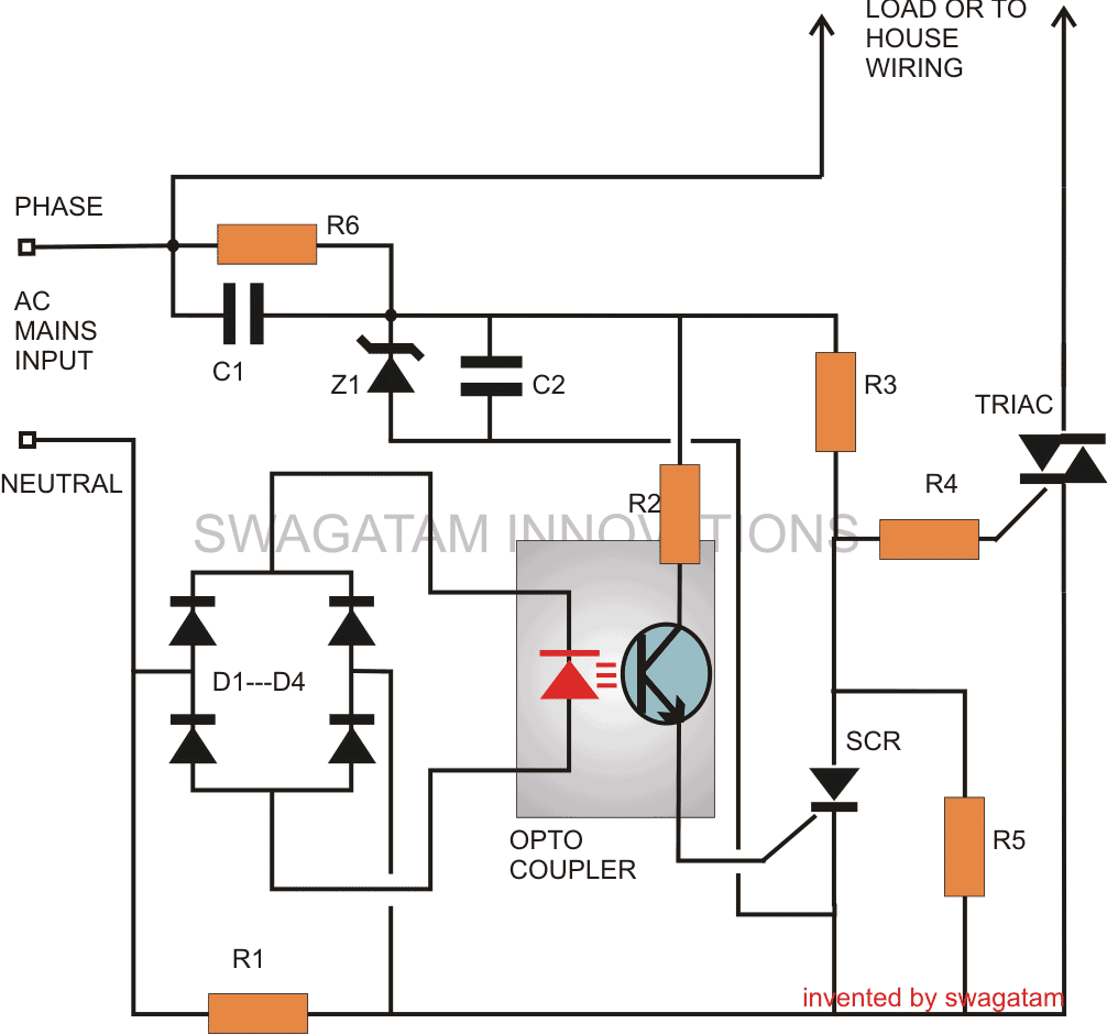
The sensing stage of the circuit in fact becomes the heart of the whole system and consists of an opto-coupler OP1.
As we all know, an opto-coupler internally consists of an LED and a switching transistor arrangement, the transistor is switched ON in response to the illumination of the built-in LED.
Thus the triggering of the transistor which forms the output of the device takes place without any physical or electrical contact rather through the passage of light rays from the LED.
The LED which becomes the input of the device may be switched through some external agent or a voltage source which required to be kept aloof from the output stage of the opto-coupler.
Why an Optocoupler is Used
In our circuit, the opto coupler LED is powered through a bridge network which obtains it voltage source from the potential generated across resistor R1.
This resistor R1 is connected in such a way that the AC mains current to the house wiring passes through it and therefore any over-load or over-current is subjected over this resistor.
During an over load or short circuit conditions, the resistor instantly develops a potential across it, which is rectified and sent to the opto coupler LED.
The opto LED immediately illuminates, switching ON the corresponding transistor.
Using an SCR for triggering the main Triac Cut out Stage
Referring the circuit we see that the opto transistor’s emitter is connected to the gate of an external SCR, whose anode is further connected to a Triac's gate.
During normal conditions, the triac remains switched ON, allowing the load connected across it to remain operational.
This happens because the SCR remains switched OFF and allows the triac to acquire its gate current through R3.
However in case of an over load or a short circuit, as discussed earlier, the opto-coupler transistor conducts and triggers the SCR.
This instantly pulls the gate potential of the triac to ground, inhibiting it from conducting.
The triac immediately switches OFF, safeguarding the load and the house wiring to which it is configured.
The SCR remains latched, until the problem is rectified and the circuit is restarted.The section comprising C1, Z1, C2 is a simple transformerless power supply circuit, used for powering the SCR and Triac circuit.
Parts List
- R1 = iron coiled wire; its resistance is calculated to produce 2 volts across it at the determined critical load conditions.

- R2, R3, R4 =100 Ohms
- R5 = 1K,
- R6 = 1M,
- C1, C2 = 474/400V
- SCR = C106,
- Triac = BTA41/600B
- Opto-Coupler = MCT2E,
- ZENER = 12V 5W
- Diodes = 1N4007