In this article I have explained a 32V, 3 amp SMPS circuit which may be specifically used as an SMPS 100 watt LED driver, rated with the same specs.
The circuit of the proposed 32 V, 3 amp smps led driver may be understood with the the help of the following points:
Circuit Operation
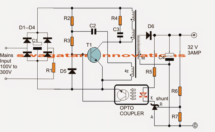
The mains voltage is rectified and filtered by the bridge network and the associated filter capacitor C1. This rectified 310 V DC passes through R1, R2 and triggers T1 into conduction.
T1 switches ON and pulls this DC to ground through the 30 + 30 primary winding inducing a steep pulse through this winding and also across the lower auxiliary winding.
This pulse across the auxiliary winding enables a negative pulse to be generated at the junction of R1/R2 which momentarily sinks the base drive to ground such that T1 now shuts off.
In the meantime C2 charges up drying up the auxiliary winding impact, and allows T1 with a fresh triggering potential at its base.
T1 conducts yet again and the cycle keeps repeating at a frequency determined by the value of R2/R3/C2 which could be around 60 kHz here.
This rapid switching induces a corresponding voltage and current across the secondary winding which may be well over 32 V, 3amps AC as per the given winding details.
The above voltage is appropriately filtered by C4 and applied across R6, R7 for feeding the shunt regulator and the opto coupler stage.
R6 is appropriately adjusted such that the output voltage settles to about 32 V.
The Shunt Regulator
The shunt regulator instantly activates the opto in case the voltage tends to rise above the set value.
The opto in turn "kills" the base drive of T1 temporarily disabling the primary operations until the output potential is restored to the correct value, the opto now releases T1 and allows the operations to work normally, only until the output rises again to initiate the opto yet again, the process keeps repeating ensuring a constant 32 V at the output, for driving the 100 watt LED module safely
Circuit Diagram of 32V 3A LED Driver for 100 Watt LED

The transformer is wound over a standard EE ferrite core having a central cross sectional area of at least 7 square mm.
Referring to the figure, the upper two primary winding are made up 30 turns of 0.3 mm diameter super enameled copper wire.
How to Wind the Ferrite Transformer
The lower primary auxiliary primary winding consists of 4 turns of the same wire as above.
The secondary is wound with 22 turns of 0.6mm super enameled copper wire.
The procedures are as follows:
- First begin winding the upper 30 turns, secure its ends on the bobbin leads by soldering, and put a thick layer of insulation tape over these turns.
- Next, wind the secondary 22 turns and solder its end terminals on the other side of the bobbin leads, put a layer of thick insulation tape.
- Over the above layer start winding the auxiliary 4 turns and as above secure the ends appropriately on the primary side leads of the bobbin, again put some layers of insulation over this,
- Finally, wind the second 30 primary turns starting from the previous 30 turn end, and secure the end over one of the leads of the bobbin on the primary side.
- Cover the finished winding with additional layers of insulation tapes.
- Make sure you remember the terminated leads properly so that you don't make incorrect connections with the circuit and cause a possible fire hazard.
Parts List
All 1 watt, CFR
- R1 = 10E
- R2 = 1M
- R3 = 470E
- R4 = 100E
All 1/4 watt MFR 5%
- R5 = 470E
- R6 = preset 22k
- R7 = 2k2
- C1 = 10uF/400V
- C2 = 2.2nF/250V
- C3 = 220pF/1kV
- C4 = 2200uF/50V
- D1---D4 = 1N4007
- D5, D6 = BA159
- shunt regulator = TL431
- opto = 4n35
- T1 = MJE13005
Useful Feedback from Mr. Kanicaras about the above circuit
Well, I tried experimenting with transformer, and doing so, I found quite a few things about the circuit:
First of all (unfortunately), this circuit is inappropriate as power source for the power supply, because the transistor blows, when circuit is not loaded (or is loaded too little).
It works well only with the load (such as 100W LED) connected to it all the time. Learned it the hard way – blew three transistors. I think that TL 431 is the culprit here. It is rated only 37V Cathode to Anode voltage.
When circuit is unloaded, it struggles to regulate the voltage at 32V (very near its own brake down voltage) and after 30 seconds or so it stops regulating (maybe because of the sporadical pulse larger than 37V) and the voltage goes up through the roof, taking down the transistor (I think through the feedback coil, because of the sharp voltage increase in it).
Secondly, I think that there are too many turns in secondary coil. 22 turns can give more than 70V unloaded (saw this number after loss of regulation, just before transistors blew) I think, that 15 or even 10 turns would be enough for 32V at the output (winding 2 or more wires in parallel).
By the way, increasing C2 capacitor value to 10 nF or more, decreases the frequency of the oscillation to human audible range (~14 kHz, checked on oscilloscope and also faintly herd it). So, I guess, its not such a good thing after all ;).
The ferrite core, that I got, came from a very old ATX so I'm not sure that it is "standard"
I found another bigger transformer. I'm going to disassemble it and try to use it in this power supply
I'll certainly try parallel strand "tactics".
Besides that, I'm going to buy some parts (including 220 pF capacitor and 4n35 opto), because, interestingly, I "fried" R5 resistor by accidently shorting the output of the power supply (while trying to connect the small light bulb :).
The lead welded itself to the light bulb and in 1 or 2 seconds (that's how long it took to disconnect it) R5 went up in smoke.
I guess that's one of the disadvantages of this power supply – you cannot short it under any circumstances. I imagine what it would be like if it was not 4 W (in my case) but fully functional power supply at 100 W.
Before I "fried" R5 resistor I tried this power supply with 120V AC input (I have DIY 100W 220V/220v/110V isolation transformer) and it gave less voltage and power than with 220V. Is that normal (is this power supply calculated only for 220V mains)?
Potential Improvements
I didn't give up on this circuit, and it paid off I replaced the shunt regulator – the circuit worked a little bit better (gave a bit more power).
But the most important change occurred, when I decided to change C2 capacitor (its value in my prototype circuit was a bit off ~1.99 nF).
When I put 2.2 nF capacitor in, the power output grew a bit more. Then I decided to increase it again and when I reached 10 nF the output was reaching ~40W (20V at ~2A and that's with my very first small transformer).
The second thing that happened (after I increased C2 value) was, that transistor started heating up quite rapidly (in my prototype board I didn't attach the heat sink to it yet, I just switch it on for a short periods of time).
I think, that this shows, that there is something wrong with the parameters of the transformer itself (maybe, that's why adapting the circuit to the transformer helped?)
I don't really know, if it's the right way to go though.