This one transistor cheap battery charger circuit is designed to automatically switch OFF the supply to the battery as soon as the battery has reached its full charge level.
A very simple single transistor automatic battery charger circuit is I have I have explained in this article, which uses just a single transistor for the voltage detection as well as for automatically disconnecting the battery from the supply when it gets fully charged.
Circuit Operation
As shown in the diagram we can see a straightforward configuration where a solitary transistor is connected in it’s standard operating mode. The circuit functioning may be understood with the help of the following points:
Considering the battery to be charged is a 12 volt battery, we know that it is advised to charge the battery until it reaches between 13.9V to 14.3 volts.
The transistor base voltage is adjusted using the preset P1, such that the transistor just conducts and operates the relay at around 14 volts.
How to Adjust the Cut of Thresholds
This adjustment becomes the high voltage trip point of the circuit and is used to switch OFF the charging voltage to the battery when it gets fully charged or its voltage reaches around 14 volts.
The lower trip point of the circuit cannot be adjusted as this circuit is too simple and does not incorporate the low voltage detection feature.
However the transistor is itself equipped with a switch OFF feature in case its base voltage becomes too low.
Typically a general purpose transistor like the one which is shown (BC547) when adjusted to switch ON at 14 volts may have the lower threshold of around 10 volts, when it might get just switched OFF.
This wide voltage difference between the high set threshold and the lower natural threshold is because of the involved big hysteresis with the design. This acts like a natural hysteresis in the design.
The lower threshold of 10 volts is dangerously low and we cannot wait for the circuit to restart the charging process until the battery voltage falls to this dangerous 10 volts level.
Allowing the battery to discharge down to 10 volts can make the battery flat permanently and reduce its life. . Therefore to eliminate this issue the circuit needed to somehow reduce the hysteresis level. This is done by introducing a couple of diodes at the emitter of the transistor.
We know that normally a 1N4007 diodes would drop around 0.7 volts across it and two if them would make a total of 1.4 volts. By inserting the two diodes in series with the emitter of the transistor, we force the transistor to switch off 1.4 V earlier than its normal specified limit of 10 volts.
Therefore now the lower operating threshold of the circuit becomes 10 + 1.4 = 11.4 volts, which may be considered just OK for the battery and for the automatic restart of the charging process.
Having both the thresholds updated as per the standard charging requirements, we now have an automatic automotive battery charger that’s not only cheap to build but also smart enough to take care of the battery charge conditions very efficiently.
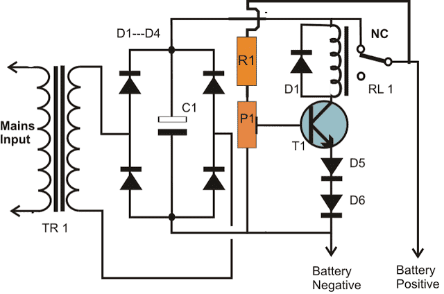
Circuit Diagram
Parts List for the proposed one transistor automatic battery charger circuit
R1 = 4K7 =1
P1 = 10 K preset =1
T1 = BC547B = 1
Relay = 12 V, 400 Ω, SPDT = 1
TR1 = 0 - 14V, current 1/10th of the battery Ah = 1
Bridge diodes = 1N5408 = 4
Emitter diodes = 1N4007 = 2
C1 = Electrolytic capacitor100 µF / 25 V = 1
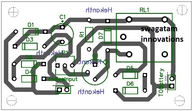
PCB Design
How to Calculate the Components
Transformer Output Voltage
The transformer (TR1) steps down the mains input to a lower AC voltage for rectification.
Let VAC be the secondary RMS voltage of the transformer.
Peak voltage after rectification:
Vpeak = VAC × √2
Rectifier and Filtering
The bridge rectifier (D1 to D4) converts AC to pulsating DC.
The capacitor C1 smooths the rectified DC voltage.
The ripple voltage (Vripple) can be calculated as:
Vripple = Iload / (f × C1)
- Where:
- Iload = Load current (charging current)
- f = Mains frequency (typically 50Hz or 60Hz)
- C1 = Filter capacitor value in Farads
Base Resistor and Potentiometer (R1 and P1)
R1 and P1 form a voltage divider to bias the transistor (T1).
Voltage across the transistor base-emitter junction (VBE) controls the transistors conduction:
VBE = (Vout × R1) / (R1 + P1)
Where Vout is the output voltage from the rectifier.
You must Adjust P1 to set the battery cut-off voltage. The transistor will conduct when:
VBE ≥ 0.7V (for silicon transistors)
Relay Activation
The relay (RL1) will be activated when the transistor T1 conducts completing the circuit.
Relay coil current:
Irelay = (Vout - VCE(sat)) / Rrelay
- Where:
- Vout = Output voltage
- VCE(sat) = Saturation voltage of the transistor (typically ~0.2V)
- Rrelay = Resistance of the relay coil
Diodes (D5 and D6)
D5 and D6 will provide the reverse voltage protection and prevent over-discharge of the battery.
Voltage drop across these diodes:
Vdrop = n × Vf
- Where:
- n = Number of diodes (2 in this case)
- Vf = Forward voltage drop of each diode (typically 0.7V for silicon diodes)
Battery Charging Current
Charging current will depend on the difference between the charging voltage (Vch) and the battery voltage (Vbat) and the resistance in the circuit:
Icharge = (Vch - Vbat) / Rseries
Where Rseries is the series resistance which may include internal resistance of the battery and circuit wiring.
Relay Cut-Off
The relay will disconnect the battery when the battery voltage exceeds a threshold set by P1 and R1.
Cut-off voltage should be approximately:
Vcut-off = VBE + VD5 + VD6
Practical Adjustments
You must Fine-tune P1 to set the desired battery cut-off voltage based on the battery type and specifications.
You must Select the R1 and the C1 to ensure proper filtering and biasing.
Practical Solved Example for a 12V 7 Ah Lead Acid Battery
Let us assume we want to charge a 12V 7 Ah lead acid battery with auto cut and self restoration. Then we can calculate the above parameters in the following manner:
Calculating the Transformer Output Voltage
To charge the 12V battery up to 14V, the rectifier's output voltage needs to exceed this voltage after accounting for diode drops and ripple.
Assuming a full-wave rectifier with two diodes in series:
Total diode drop = 2 × 0.7V = 1.4V
Required minimum peak voltage = 14V + 1.4V = 15.4V
RMS voltage of the transformer secondary:
VAC = Vpeak / √2 = 15.4 / 1.414 ≈ 10.9V RMS
Choose a transformer with a secondary RMS voltage of 12V to ensure some margin.
Calculating the Filter Capacitor (C1)
The filter capacitor smooths the rectified DC. Let the load current (Iload) be the charging current.
For lead-acid batteries, a safe charging current is around 10% of the battery capacity:
Iload = 0.1 × 7 Ah = 0.7 A
Assuming a mains frequency of 50Hz, the ripple voltage should be small (e.g., 1V). The required capacitance is:
C1 = Iload / (f × Vripple) = 0.7 / (50 × 1) = 0.014 F = 14,000 μF
Use a capacitor with a value of 14,000 μF (or higher) and a voltage rating above the rectified voltage (e.g., 25V).
Setting the Cut-Off Voltage (P1 and R1)
The cut-off voltage is set to 14V. The transistor T1 turns on when its base-emitter voltage VBE reaches ~0.7V.
Voltage across the R1-P1 divider must match this threshold:
VBE = (Vout × R1) / (R1 + P1) = 0.7 V
Now let us Rearrange the terms to calculate the ratio of R1 and P1:
R1 / (R1 + P1) = 0.7 / 14 = 0.05
Let R1 = 1 kΩ, then P1 = 19 kΩ.
Use a 1kΩ resistor for R1 and a 20kΩ potentiometer for P1 to allow fine adjustment of the cut-off voltage.
Calculating the Relay Specifications
Relay must be able handle the charging current,, and operate at the rectified voltage.
Coil voltage: Vcoil = Vout - VCE(sat) ≈ 14 - 0.2 = 13.8V
Coil resistance: We should Choose a relay with a coil resistance such that:
Irelay = Vcoil / Rrelay
Ensure that Irelay matches the transistors current-handling capability (typically < 1A for small transistors).
Calculating the Charging Current
With a 0.7A charging current and the series resistance in the circuit we will calculate the total resistance needed as:
Rseries = (Vch - Vbat) / Icharge = (14 - 12) / 0.7 ≈ 2.86 Ω
Use a resistor close to 2.7Ω or 3Ω, rated for power dissipation:
P = Icharge² × Rseries = 0.7² × 2.86 ≈ 1.4 W
We must Choose a resistor rated for at least 2W.
Finalized, Component Values:
- Transformer: 12V RMS secondary, capable of 1A or more.
- Filter Capacitor (C1): 14,000 μF, 25V.
- Base Resistor (R1): 1kΩ.
- Potentiometer (P1): 20kΩ.
- Series Resistor (Rseries): 2.7Ω, 2W.
- Relay: 12V coil voltage, capable of switching 1A or more.
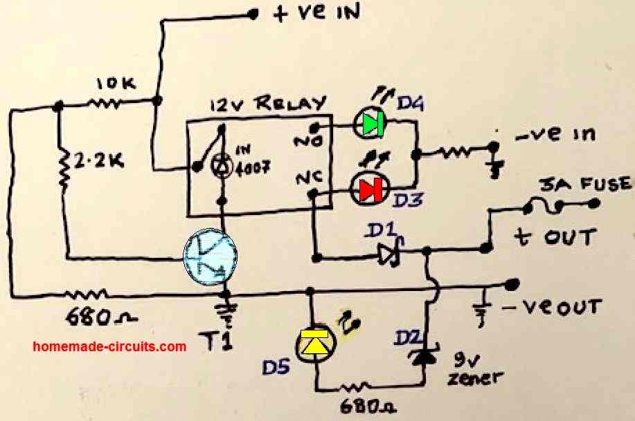
Single Transistor Battery Charger Circuit with Auto Cut-off
In this article I have explained a very simple automatic battery charger circuit using a single transistor and a relay as the main components. Despite being extremely simple, the design exhibits an auto cut-off feature when the battery reaches full charge level. The circuit also has a 3-LED indicator for indicating the various charging stages of the battery.
Parts List
- Resistors are all 1/4 watt 5%
- 10 K = 1no
- 680 Ohms = 3nos (2 resistors connected with the LEDs)
- 2.2 K = 1no
- Semiconductors
- 1N4007 = 1no
- 9 V 1/2 W zener diodeD2 = 1no
- D1 Schottky diode SR360/SR560 = 1no
- T1 Transistor can be BC547, BC548/2N3904/2N2222 = 1no
- D3 RED LED 5mm 20 mA = 1no
- D4 Green LED 5mm 20 mA = 1no
- D5 Yellow LED 5mm 20 mA = 1no
- Relay 12V 400 mA = 1no
How the Circuit Works
Referring to the above single transistor automatic battery charger circuit, the working details can be understood with the following points:
Initially, the discharged battery which needs to be charged is connected across +OUT and the ground -Ve OUT of the circuit.
The +OUT of the charger circuit goes to the positive terminal of the battery via the 3 amp fuse.
The GND line of the -VE OUT goes to the battery negative terminal.
After this, the circuit is powered through a 13.5 V regulated DC supply. The positive is connected to the +Ve IN point, and the negative is connected to the - Ve in point.
The above DC enters the circuit and passes through the pole of the relay and reaches the N/C contact of the relay.
From the N/C contact of the relay, the 13.5 V reaches the battery (+) terminal D1 and the 3 amp fuse.
Let's assume the voltage of the discharged battery is 11 V. The 13.5 V of the input supply is now dragged down to the 11 V value.
The battery now begins charging.
The RED LED gets the operating voltage via the relay N/C contact and illuminates, indicating that the battery is charging.
The calculated values of the resistive divider (10 K and 680 Ohms) at the base of T1 ensures that T1 remains switched OFF as long as the battery is charging and its terminal voltage is below 13.5 V.
As the battery charges, at some point of time its terminal voltage reaches an intermediate higher value. This illuminates the yellow LED via D2, indicating the charging status of the battery.
Finally, after many hours of charging, the battery voltage reaches the set full charge level of 13.5 V. When this happens, the base potential of transistor T1 becomes sufficiently high forcing the transistor to conduct.
The transistor now switches ON and activates the relay, whose contacts now changeover from N/C to N/O.
This cuts off the supply to the battery and the charging of the battery is inhibited. In this way the automatic battery cut-off is executed when the battery reaches the set full charge level.
The green LED connected with the N/O contact of the relay lights up indicating that the battery is now fully charged, and the charging has been cut off.
Notes:
The above explained single transistor 12 V automatic battery charger circuit was tested and found to be working perfectly OK.
The battery used for the testing was a 12 V Lead Acid Battery
Full charge level cut off level was set to 13.5 V, and the input DC supply was 14.5 V.
Since the full charge cut off level is determined by the 10 K and the 680 ohm resistors at the base of the transistor, you can adjust these values to change the full charge cut off level to any other appropriate value.
Remember, the discharge battery must be always connected first before powering the circuit. Otherwise the relay will switch ON and move to the N/O contacts and then connecting the battery will keep the battery cut off.
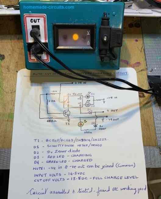
Prototype Images
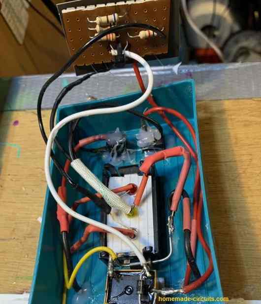
The first image below shows the internal construction of the single transistor automatic battery charger circuit. We can clearly see the complete assembly consisting of the resistors, transistor, relay, diodes, and the LEDs.
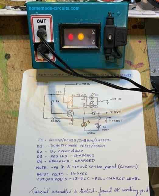
The next image below shows the testing procedure of the circuit, which is charging an attached battery. The RED and the Yellow LEDs are switched ON, indicating the ongoing charging process, and the battery has reached an intermediate charging stage, approximately at around 13 V.
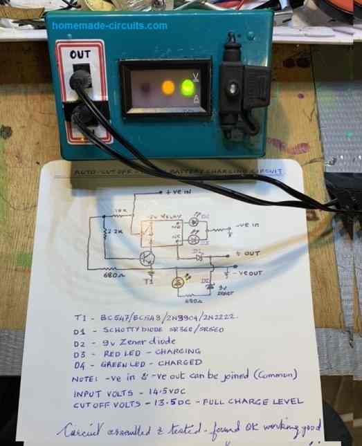
The next image below shows the battery is fully charged and the relay has cut off the charging supply to the battery. The green and yellow LEDs indicate the fully charged status of the battery.
The last image below shows SoC status of the battery, indicated by the illuminated yellow LED. This happens when the power to the circuit is switched off and the battery is still connected with the circuit.