

The post explains a high current Li-Ion battery charger circuit which can be used for charging any high current, such as 2S3P, 3S2P battery packs. It can be also used for charging other similar high Ah rated Li-ion battery from a car or a truck battery. The idea was requested by Mr. Neil

Charging a 8800 mAh Li-Ion Pack
This is perhaps very cheeky of me to ask for your help, but my design skills are limited in electronics and as a volunteer my budget is limited.
I am a volunteer for a local Search and Rescue organisation (Suffolk Lowland Search and Rescue), we are on call 24hrs a day 365 days a year, our work involves finding anyone who has gone missing in Suffolk (and bordering county’s).
Search often take place during the hours of darkness and we have a particular need for good torches, which need to be ready for action at a moments notice.
I am part of the mountain bike rescue team, we cover ground very quickly and can search paths much faster then foot teams, lights are again very important and I hope this is where you can help.
I have recently bought a Cree LED light for my bike, it is powered by a 8.4v Li-ion 8800mAh battery pack, I have 2.
These units came with a mains powered charger (240v UK) and what I would like is to be able to charge them in the car where the bike is kept.
I noticed you have already designed some charging circuits for this type of battery and I wonder if you could modify your design to be able to charge from a 12v car circuit to these specification batteries.
The car circuit will be switched with the ignition. I am very capable of constructing the circuit, it’s just my design skills that are limited!
I very much appreciate anytime you spend on this, it will help not only me, but potentially any lost sole in Suffolk.
Kindest regards,
Neil.
The Design
The shown high current Li-Ion battery charger circuit is featured to charge any Li-ion battery upto 5 AH with the shown IC2, or for 10AH batteries if IC2 is appropriately replaced with a LM396
The LM338 IC2 is a versatile voltage regulator IC which can be specifically configured for charging Li-Ion cells with the essential features such constant current and constant voltage.
The above design is configured as a constant voltage Li-ion charger, since we assume that the input supply to be a constant current.
However in case the input supply is not current limited, the IC2 can be enhanced with an effective constant current feature. We will discuss this at the end of this explanation.
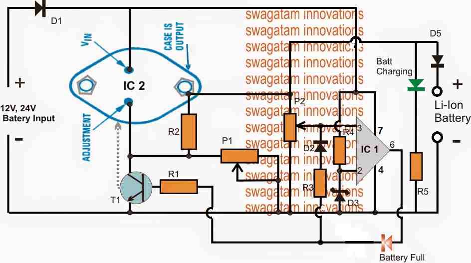
The design consists of two fundamental stages, the IC2 voltage regulator stage and the IC1 over charge cut-off stage.
IC2 is configured in its standard voltage regulator form, where P1 functions as the control knob and can be adjusted to generate the required charging voltage across the connected Li-ion battery at the output.
IC1 pin3 is the sensing input of the IC and is terminated with a preset P2 for facilitating the over charge voltage level adjustment.
The preset P2 is adjusted such that when the battery reaches its full charge value, the voltage at pin3 just becomes higher than pin2, resulting in an instant high at pin6 of the IC.
Once this happens the high from pin6 latches on to pin3 with a permanent high via R3, D2, freezing the circuit in that position. Remember this latching network is optional, you can remove it if you wish, but then the the Li-ion battery will not be permanently cut-off, rather intermittently switch ON/OFF depending on the full charge level threshold of the battery.
The above high is also delivered at the base of the BC547 which immediately grounds the ADJ pin of IC2 forcing it to shut down its output voltage thereby cutting off the voltage to the Li-ion battery.
The Red LED now illuminates indicating the full charge level and the cut off conditions of the circuit..
Circuit Diagram

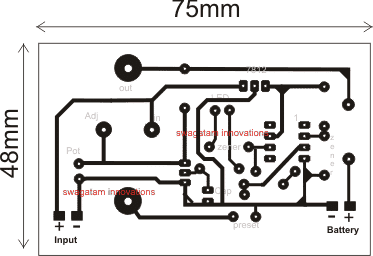
PCB Design
Parts List fro the proposed high current 12V/24V li-ion battery charger circuit
- R1, R5 = 4K7
- R2 = 240 Ohms
- P1, P2 = 10 K Presets
- R3, R4 = 10K
- D1, D5 = 6A4 diode
- D2 = 1N4148
- D3, D4 = 4.7Vzener diode 1/2 watt
- IC1 = 741 opamp for 12V input, LM321 for 24V input
- IC2 = LM338
How to Set up the circuit.
- Initially do not connect any battery at the output, and rotate P2 so that its slider touches the ground end, in other words adjust P2 to make pin3 to zero or ground level.
- Feed the input voltage, adjust P1 for getting the required level of voltage across the output where the battery is supposed to be connected, the green LED will be lit up in this position.
- Now very carefully move P2 upwards until the the red LED just illuminates and latches in that position, stop moving P2 any further, confirm with green LED shutting of in response to red LED illumination.
- The circuit is set now for the required high current Li-ion charging from a car battery or any 12/24V source..
Adding a Constant Current Feature in the above Design
As shown below, the above design can be further improved by adding a current control feature, which makes the proposed high current Li-ion charger circuit perfect with the features of CC, and CV, that is with constant voltage and constant current attributes.
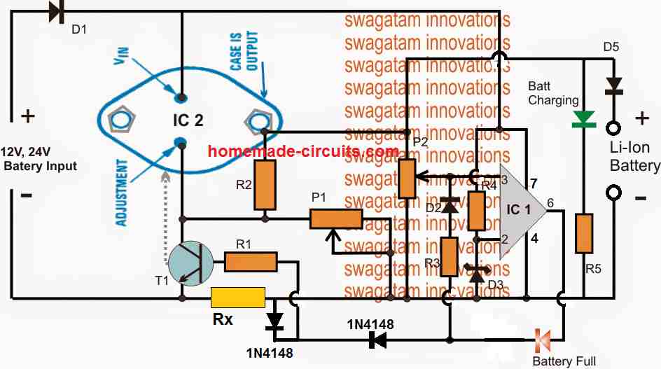
Note: The latching of the op amp is not compulsory, hence the D2 and R3 can be removed, and the circuit will still work nicely and automatically cut-off when the battery is fully charged.
Simplified Design
While the above explained circuits are great with their features and working, the use of LM338 makes the design a bit complex, and costly.
A little tinkering reveals that the application could rather be implemented using only a single opamp and a BJT based current control as shown below:

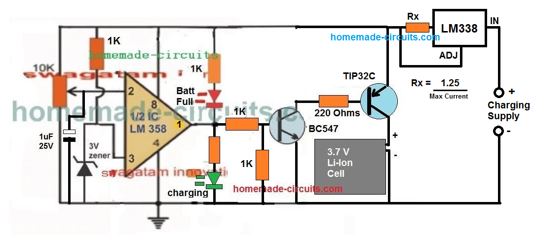
A 1uF capacitor is introduced at the inverting input of the IC, which ensures that the IC always starts with its output at positive high when powered. This in turn allows a guaranteed switch ON of the output transistor, and enables the connected battery to lock in with the charging process.
The concept has been tested thoroughly, the video proof can be seen here.
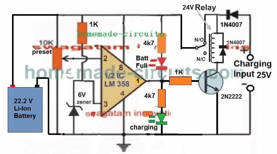
22.2 V Li-Ion Battery Charger Circuit
The following diagram shows a simple yet very accurate Li-Ion battery charger circuit with cut off. This charger can be used for charging a 6S Li-Ion battery rated at 22.2V.

WARNING: IN ALL THE ABOVE CONCEPTS, TEMPERATURE REGULATION FOR THE BATTERY IS NOT INCLUDED, SO PLEASE MAKE SURE TO ADJUST THE CURRENT TO A LEVEL WHICH DOES NOT CAUSE THE BATTERY TEMPERATURE TO REACH ABOVE 40 DEGREES CELSIUS.