
The TIP127 is a PNP Darlington transistor commonly used for high-power switching applications. Here is the complete datasheet for this transistor:
Electrical Characteristics:
- Collector-Emitter Voltage (VCEO): 100V
- Collector-Base Voltage (VCBO): 100V
- Emitter-Base Voltage (VEBO): 5V
- Collector Current (IC): 5A (continuous), 8A (peak)
- Base Current (IB): 50mA (continuous), 100mA (peak)
- Power Dissipation (PD): 2W
- Minimum hFE or DC Current gain: 1000
Thermal Characteristics:
- Junction Temperature (Tj): -65°C to 150°C
- Thermal Resistance - Junction to Case (RθJC): 3.125°C/W
- Thermal Resistance - Junction to Ambient (RθJA): 62.5°C/W
Pin Configuration:
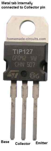
As shown in the above figure, the TIP127 transistor has three pins: the collector (C), the base (B), and the emitter (E). The pinout configuration is as follows:
- Pin 1: Base (B)
- Pin 2: Collector (C)
- Pin 3: Emitter (E)
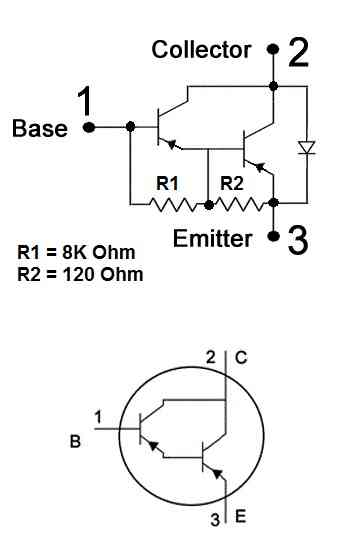
Internal Darlington Configuration
The TIP127 is a PNP Darlington transistor which has two PNP transistors configured with each other, as shown in the following diagram:
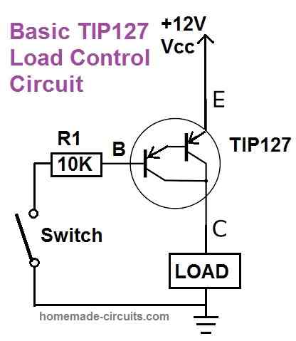
How to Switch ON TIP127 Transistor
Since the TIP127 is a PNP transistor, it can be switched ON by applying a negative potential to it base pin, as shown in the following circuit diagram:
Package Information:
The TIP127 transistor is available in the TO-220 package, which is a through-hole package with a single mounting hole. The package dimensions are as follows:
- TO-220 Package: 10.67mm x 15.87mm x 4.83mm
Typical Applications:
The TIP127 transistor is commonly used in high-power switching applications, such as:
- Power supplies
- Motor control
- Lamp dimming
- Solenoid control
- Audio amplifiers
- High-current drivers
Limitations:
- Maximum Collector Current: 5A (continuous)
- Maximum Power Dissipation: 2W
- Maximum Voltage: 100V
Other Features:
- Darlington Configuration
- High DC Current Gain (hFE)
- Low Saturation Voltage (VCEsat)
Note: This information is taken from the TIP127 datasheet published by ON Semiconductor. Actual values may vary based on specific manufacturer and production batch.