
In this article I have explained an alternator power booster circuit which was unveiled by one of the keen followers of this blog, Mr Michael Mbamobi. I have explained more about the details.
Technical Specifications
There is this circuit I want to show you. I want to show you the circuit through Homemade Circuit or Brighthub.
I didn't see how I can upload picture there. Please direct me I can sent this through Homemade Circuit. Anyway I uploaded the picture here! see the circuit and find out what these our Nigerian Guys are up to. I only hear about this type of device here in Nigeria.
I bought it and disassembled it. With your ability as Engr. Swagatam Majumdar, you can build a better device that can perform this same thing without depending on their own construction.
The folks call this an alternator power booster! It enables small gensets support loads bigger than their coils and feel alright with it without yearning!
I disassembled it carefully because D1, R1, R2, C2 and Q1 are obscured inside a glue like paste.
AC IN is from a small 650VA Generating set which is normally incapable of powering the connected loads.
The diode polarity and the value is not certain but this is its place in the circuit. It got broken while dismantling the glued circuit.
Q1 couldn't be traced either because the print was scraped of by the manufacture.Only its pin#1 and pin#3 responded to the DMM, it read zero like a dead diode, pin#2 does not read with any other pin at all. Pin#4 which is the tab is also unconnected.....just cannot figure out the device or its specs.
The diode D1 is blue in color, small glass type.
Solving the Circuit Request
Dear Michael,
It looks like an AC voltage booster circuit to me. Q1 is probably a power triac, the diode might be a diac DB-3, I am assuming this since it's small glass type and blue in color.
I would be addressing this circuit in my blog very soon....kindly stay tuned for the updates in my blog.
Thanks and Regards.
Circuit Explanation
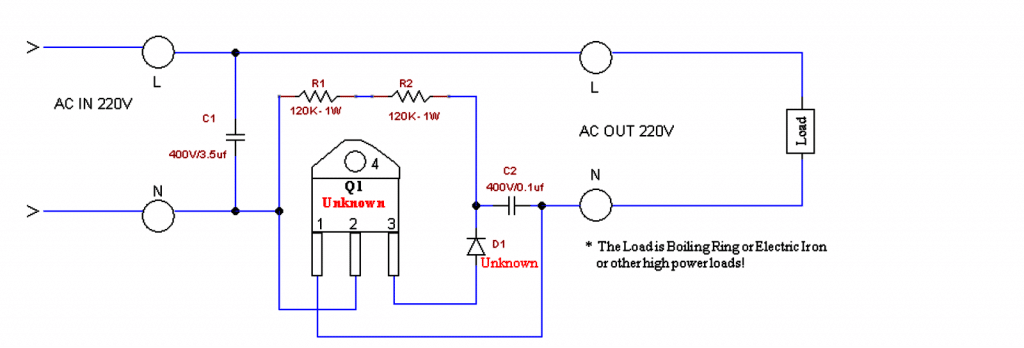
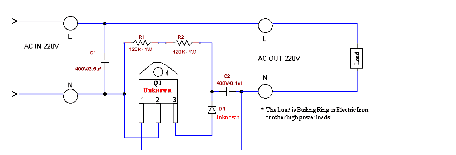
This circuit is a simple AC voltage booster designed for supplying boosted voltage to high-power resistive loads like electric irons or boiling rings. Here's how it works:
Working Principle:
Capacitive Voltage Divider (C1)
The capacitor C1 (3.5µF, 400V) works like a reactive voltage dropper to provide a phase-shifted voltage for triggering the TRIAC (Q1).
It limits the current flowing into the gate of the TRIAC.
Gate Drive for the TRIAC (Q1)
Resistors R1 and R2 (120K, 1W each) form a voltage divider network which ensures a controlled gate drive for Q1.
The combination of D1 (Unknown, but likely a Diac) and C2 (0.1µF, 400V) creates a triggering delay, which allows phase control of the AC waveform.
Switching Action of TRIAC (Q1)
The TRIAC remains off until the breakover (firing) voltage of D1 (could be a Diac like for example a DB3) is reached.
When this happens then the D1 conducts, which sends a sharp pulse to the gate of Q1, turning it on.
The TRIAC then conducts ON, allowing the AC power to reach the load.
Voltage Boosting Mechanism
The phase angle of TRIAC conduction is controlled, which modifies the effective RMS voltage applied to the load.
By partially delaying the triac conduction, the circuit makes it possible to increase the peak voltage for the load.
The increase of the voltage across the load is achieved by extending the conduction duration of the AC cycle.
Main Features:
It Increases output voltage above input voltage (may not bee a true step-up transformer action but rather a phase-controlled voltage boost type).
It will Work effectively with resistive loads (boiling rings, irons, etc.).
This concept Uses phase angle control to regulate output power.
Capacitor C1 is a crucial component which helps to boost the voltage by acting as a reactive impedance.
Limitations:
This design is Not suitable for powering inductive loads (motors, transformers).
Here, the Voltage boost depends on the load resistance and the phase angle.
It Can create harmonics and waveform distortion in the AC supply line of the grid.
Mains Voltage Booster using Two Capacitors and Two Diodes
The above concept can also be implemented with the following circuit which is simpler than the above and is also a lot cheaper.
The capacitor ratings may be modified and experimented with as per the load, and individual preferences.
However this circuit can be used only for heater applications such as irons, heaters, geysers, ovens, toasters, blowers, dryers, hot air gun etc.
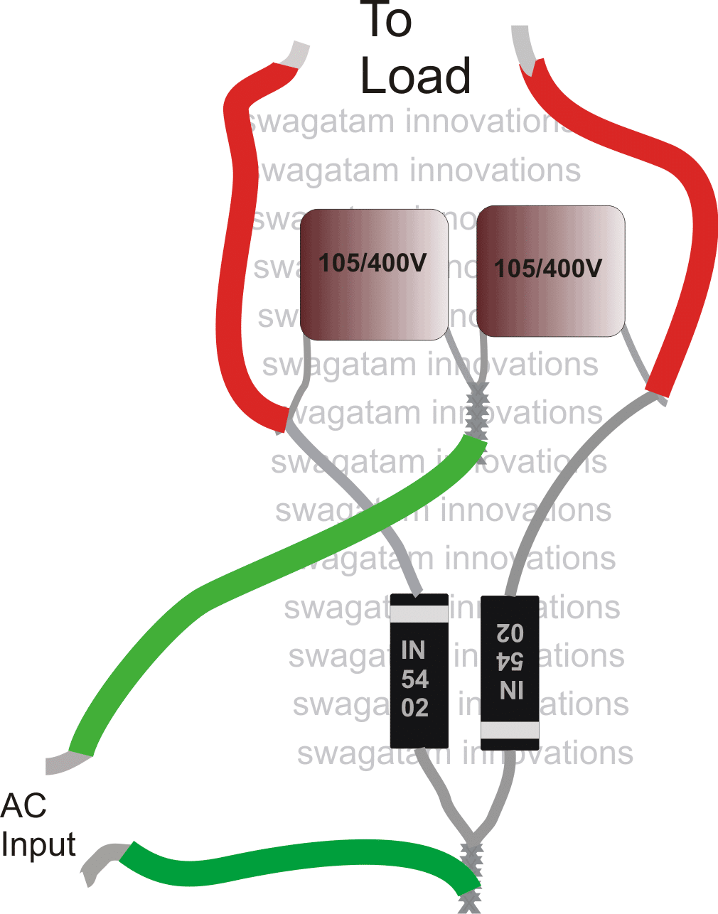
Please use 1N5408 diodes instead of 1N5402, mistakenly shown in the above diagram.
Video Proof
