Before we go ahead with the full concept and working of the Higgins Engine, I want to tell all our readers something very important. Recently I got a very kind and generous email from one of our respected readers Mr. Higgins. I am thankful and honored to receive such an in-depth and original contribution from him. That email is not just an introduction but actually a gift for everyone who believes in free energy and innovation from Nature.
Mr. Higgins told us that he has invented a completely new concept of producing electricity from gravity only. That means, no fuel, no sun, no wind, no chemical—just gravity in, and electricity out. He calls this unique technology The Higgins Engine. That is really something very rare and revolutionary.
He also said that he is not doing this for money, business, or patent. He only wants to give this idea to the public domain, so that anybody who feels inspired by it can take it forward and use it for the betterment of our future. That attitude itself deserves huge respect and gratitude.
Here is a small summary of what Mr. Higgins told us in his own words. We are putting this here as it is, so our readers can know who this brilliant person is and what exactly he shared with us:
"I am not sure if this is the right outlet for my machine, but you have many examples of producing electricity from various sources of energy from Nature. So here is the purpose of this email:
I have invented a new technology concept to produce electricity from gravity. Only gravity in, electricity out. My machine is called 'The Higgins Engine'. I have no interest in a patent, or a business, or making money off of it. I just want to give it away to the public domain. Is your outlet interested in introducing The Higgins Engine to the public? I believe that the more ideas that get out there, the better the chance of some of them working. We need that if we are going to save the biosphere.
For reference; I am a retired engineer from Boeing Phantom Works, the dedicated research and development division. I have been involved in, and created the design of, several high tech and envelope pushing programs. I have done my engineering due diligence with PHDs in Physics and Fluid Mechanics, and the unanimous declaration from them, and myself, is: The Higgins Engine Works. Gravity in, electricity out.
Gravity power is not one of your categories on your website, but free electricity is. Gravity is ubiquitous and free."
So now, with great respect and deep thanks to Mr. Higgins, I am sharing his complete concept, construction details, and theoretical working of this new gravity-based free energy machine. This could be a big step toward cleaner future and alternative energy breakthroughs. We hope many passionate engineers, students, and innovators around the world will get inspired by this and start working on building or evolving it in real life.
Climate Change and Urgent Action
The reality of climate change imposes hardship and change on all life in the biosphere. If allowed to continue unchecked, the future appears grim. Human life must adapt to the changing climate. The absolute need to replace technology that pollutes, like fossil-fueled power generation, is clear in order to stop continued pollution.
But just stopping the polluting activities will not save us. We will need to reverse what we have done at the very least, and then hope Nature can correct the rest. That means removing pollutants like CO2 from the atmosphere is imperative, and the need is NOW.
The Environment Needs Immediate Attention
Ending overfishing, and the use of technology such as nets dragging the bottom that results in destruction of the ocean environment, is imperative, and the need is NOW. Ending the creation and then dumping of pollutants and other human waste into the environment is imperative, and the need is NOW.
The Role of Energy in Recovery
The common component of these “need is NOW” activities is energy. We need enough energy to power the new infrastructure and machines that are needed to implement the changes. But power generation is proving to be one of the biggest polluters. Therefore, the need for pollution-free power generation at a cost that is manageable is the first step in the rescue and recovery of the biosphere.
Electricity and Human Capability
Ultimately for us, power is the result of the energy to put mass in motion—from wind and water to electrons. The power form most used in our time is electricity. Electrons in motion. With enough electricity, we can build machines that will do just about anything that can be done.
Fuel and Machines
The difficulty is that for human-made machines there is a need for fuel. Fuel is actually just a concentration of energy in some form. We take that fuel and process it to release the energy it brings to the system.
We then manipulate that energy to perform work (putting electrons in motion) that creates usable electricity. Coal and oil-fueled power plants, for instance. Our machines harvest from the energy available (input energy) and produce usable electricity (output power).
Gravity and Friction in the Universe
There are two real things that are ubiquitous in the universe: gravity and friction. The deepest, darkest voids of space still contain gravity and friction. Physicists have to describe detail and complexity—such as the technical definitions of “Work” and “Friction”—as their professional existence. I will try not to do that herein.
Introducing The Higgins Engine
I wish to describe, in common terms, what is happening in The Higgins Engine. I will provide some math and science and use terms like Work and Friction, but not the exacting details of professional physics.
I will be trying to communicate the concept and hardware reality for non-professionals. So, for any PhDs that may be reading this, you can use whatever parameters, calculations, and terminology that you want to, but you will have to translate the concepts described herein for yourself.
Understanding 'Concept' in Machine Development
One term that needs defining for use herein is “Concept”. A concept is the creative imagining (thoughts) of the developer. i.e..... I would like to have a machine that does “this”.
After the concept is determined, the functionality needed to implement the concept is defined. i.e..... This machine would have to do these things in this order. This stage is again just the creative imagining (thoughts) of the developer.
From Thoughts to Engineering Design
The next step is to technically define the functions—creating output-based requirements for the design to implement. i.e..... The machine shall output this specific amount of electricity. Again, just thoughts, but now written print on a page.
Then comes the actual machine engineering design. i.e..... The input connector is connected to the electronic filter that is connected to the amplifier, etc. etc. etc.
You are now talking about real things (hardware and software), not thoughts (concepts and functionality). This difference is important due to the common mistake of looking at a diagram of a conceptual function and thinking it is the engineering design.
It is a diagram that creates a picture in your mind of functionality. The functionality does not describe the design. The design is three steps away from the concept. They are not the same thing, and it is important to understand the difference.
Although I am going to use real hardware in my descriptions, the descriptions are conceptual—not actual engineering design—even though the conceptual diagram includes numbers and dimensions and some calculations.
Machines, Structures, and Nature
Now back to the machine. We design, build, and operate machines (supposedly) for our benefit. We know how to get stuff done with machines.
We feed fuel in and get wanted/needed functionality out. All technology enjoyed (or not) today is implemented via machines. To progress, we need the machines.
We are also very good at designing and building structures. These provide benefits without the requirements of fuel and power from us.
The Higgins Engine: Operated by Nature
The Higgins Engine is a structure built by us. The Higgins Engine is a machine operated by Nature. The physical architecture of the structure and its contents require Nature to manifest specific known physical phenomena, from which we harvest the output power from the machine.
Windmills are mechanical structures that we build, put in front of Nature, and Nature operates them by wind energy.
We then harvest the output power from the windmill system (including the generator) for our own benefit. The Higgins Engine implements the same concept. For normal operations, we put nothing in and reap power out.
Fuel from Nature
The big point there is fuel. A machine cannot operate without input fuel. But fuel can come from Nature.
The energy input to create wind (mass in motion) is ultimately from the sun. It heats the air, creates high- and low-pressure areas, and causes air to move. We put a windmill in front of it as input to our system. Nature provides the energy.
Harvesting Gravity: The Source Behind the Engine
The Higgins Engine does not use wind, rain, or sunshine to provide the input energy from nature for the system. The Higgins Engine harvests energy from gravity.
The gravity energy for harvest comes from two sources: the Earth and the Moon. The engine is a closed system for conservation of energy.

Basic Idea of the Higgins Engine
This diagram could be causing some academic types to start tis-tisking. But it works. The overall concept of The Higgins Engine is: nothing (from us) in, electricity (for us) out. Just like a windmill, but with gravity instead of wind.
Proof of Concept, Not Full Implementation
The practicality and application of the Higgins Engine are not a consideration at this time. This is a new protocol to harvest free energy from nature. What might come of it when the engineers get ahold of it may be expansive, or not.
This discussion provides for a proof of concept—not specifically a suggested implementation (although this one would work). If there is electricity coming out, that in itself is proof of concept. It’s a non-zero positive number that describes the output (i.e. watts). Non-polluting, cheap energy.
Harvesting Lunar Gravity via Tides
Let’s get to it and start at the input. The gravity from the moon interacts with the oceans on Earth and tides are created. A bulge in the surface of the oceans rises or falls every six hours when witnessed from a fixed location. The power of that rising and falling water is immense. It can elevate an aircraft carrier as the tide rises.
If the load (weight of the aircraft carrier) is smaller than the buoyancy required to float the carrier, the load will be elevated with the tide. That is the concept for the harvest of the moon’s gravity.
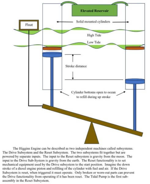
The Tidal Pump Sub-Assembly
A floating platform on the tide is attached to a mechanical structure that is anchored in position beneath the water.
The mechanical structure is the Tidal Pump sub-assembly of the engine. Think of a teeter-totter. It is anchored in the middle with the mechanical structure of a lever for the platform. When one end goes up, the other end goes down. And both ends have a load on them.
One end of the Pump teeter-totter is attached to a floating platform. The tides will raise and lower that end as long as the load is less than the buoyancy.
The structure will require the other end to rise and fall as well, in opposition. Only one side will be elevated at a time.
Push Rods, Pistons, and Water Columns
Each end of the elevation platform (teeter-totter) has the equivalent of a push rod and piston sitting on top of it.
The piston fits into an independent and solidly mounted vertical cylinder filled with seawater. The elevation platform and bottom portion of the cylinder are under water.
With proper physical pressure valve placement, when one end goes up, the piston elevates water in that cylinder. As the piston rises, the cylinder behind it refills with new water from the ocean.
Check Valves and Water Retention
The water that was elevated in the cylinder is prevented from falling back down by a pressure plate positioned and operated by the direction of the water pressure (up or down). The piston top and pressure plate allow water to pass going up and plug the cylinder for water going down.
The weight of the water in the cylinder above the pressure valve plate in one cylinder is the total load available to whatever float platform has been designed.
Cylinder Dimensions and Lifted Mass
The length of the vertical cylinder above sea level, in conjunction with the diameter, will determine the elevation and quantity of the water when it overflows the cylinder at the top. The piston stroke distance then determines the total quantity of water that is lifted over time.
Capturing Potential Energy from Nature
Work has been performed. We now have mass (a reservoir of water) at elevation in the Earth’s gravitational field. That equals potential energy in physics. I think of it as a battery holding energy.
Point is, Nature—gravity originating at the moon—has provided the energy to move mass, and we captured that energy to use as we please.
Powering the Reset Subsystem
The elevated reservoir provides the energy to power the remaining functionality of the Reset Subsystem. Controlled release of the water will fill containers attached to mechanical advantage levers (“...give me a lever and I will move the world...”).
As the reset levers travel, switches will be thrown, hardware positions will be reset, and the Drive Cylinders will be recharged. The Drive Subsystem will then be triggered to fire and do its thing.
Gravity-Powered Mechanical Movements
All of these reset functions are mechanical, and they operate by Earth’s gravity pulling down on the water in the container on the lever. When the lever reaches its travel distance, the container will open and discharge the water back into the ocean. The lever then returns to its start position, ready for the next cycle.
Main Tasks of the Reset Subsystem
The Reset Subsystem mechanical functions that must be completed include:
- Lifting the Drive Mass
A solid, specific-weight mass must be lifted to a specific altitude. This is referred to as the Drive Mass. It is a simple lever function. Mechanical connections hold that mass elevated until it is triggered to drop in freefall. - Retracting the Drive Piston
The Drive Piston in the Drive Cylinder must be retracted after the Drive functionality has fired it. This returns the piston to its start position. - Refilling the Drive Cylinder
At the same time as piston retraction, the Drive Cylinder must be refilled with recycled tank water that was used in the Drive Subsystem.
Diagram and Energy Source
The following diagram gives a good conceptual picture of functions 2 and 3 just described. This work—all of the work done by the Reset Subsystem—requires no more energy than the amount that Earth’s gravity and the water from the Elevated Reservoir can provide.

Reset Subsystem is Stand-Alone
The complete Reset Subsystem is stand-alone with respect to energy and work. It operates under known laws of physics and mechanical engineering, and is mechanically isolated from the Drive Subsystem. If the Reset functionality works, the Drive has to fire. It physically has no option.
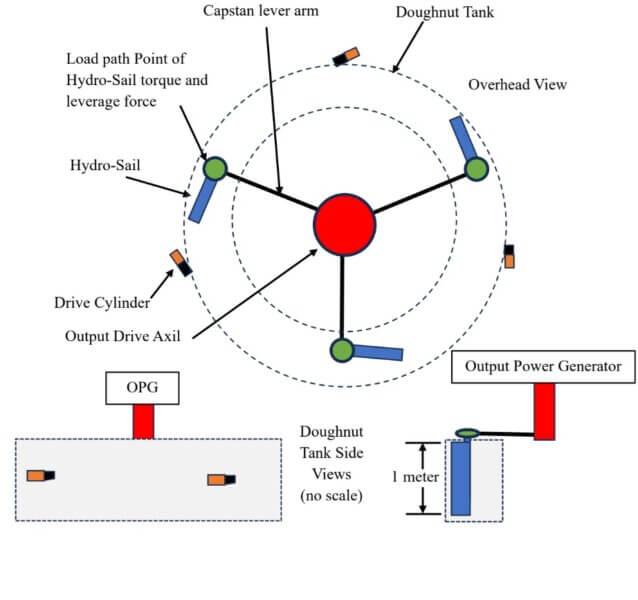
Basic Design of the Drive Subsystem
The Drive Subsystem is basically a round river of accelerating water, in a contained channel. A pipe full of water accelerating around in a circle.
A horizontal paddle wheel is positioned with the paddles continuously in the flowing water, and turning a drive axle through mechanical advantage. The drive axle, with torque and rpm, is mechanically linked to an electric generator. Electricity comes out.
Simple Mechanics, Deep Physics
The Drive Subsystem, while mechanically non-complex, reaches fairly far into the depths of physics, and the math that describes those physics. The mechanical concept creates a dynamic physical architecture of solid, liquid, and energy environments.
This combination of individual environmental phenomena requires the natural formation of various liquid and energy currents, pressure zones, and energy densities acting on a solid Hydro-Sail. The Hydro-Sail provides mechanical advantage in both torque and leverage forces for all forces acting upon the sail.
The combined results provide the compilation and concentration of forces to enable and sustain Higgins Engine operation and production of the electric power output from the engine.
Beginning of Energy Pulse
Operations of the Drive Subsystem begin in the solid environment with a dead weight mass falling a specific distance under gravitational acceleration. At that distance, the mass with velocity strikes a mass at rest.
The kinetic energy then jerks the mass at rest to virtually the same velocity of the falling mass—virtually instantaneously—when considering the mass at rest will only travel one centimeter. The time is very short.
With mechanical advantage for velocity, a piston is jerk-stroked in its Drive Cylinder that forces a volume of water to be jerked into the current of the round river flowing water. The new input water appears in the middle of the volume of water, such that the cubic volume of the flowing water must expand to accommodate the new mass.
That expansion behavior manifests in the jerk environment (really fast). This begins the fluid mechanics physics involvement in energy management and mass behavioral characteristics.
The Doughnut River Begins to Flow
The input shot of water causes the water in the tank to accelerate. This is from both physical forces from the water and energy transmission in water—different forms of force. The Higgins Engine is now a doughnut-shaped tank with an accelerating river flowing around in it. Lovingly called the Doughnut Tank and the Doughnut River.
Each shot of water results in an energy pulse propagating and dissipating in the liquid environment around the Doughnut, at the speed of sound in water (for this discussion approx. 600 km/hr).
With intentionally timed and synchronized pulsed shots entering the unobstructed Doughnut River—plus each physical jerk from the additional mass entering the water—the river will, over time, be accelerated to the velocity jerk speed of the input shots.
This is now a battery of energy in the form of water velocity (mass in motion). That is a calculable energy factor.
Harvesting Energy with Load
Approaching the top of the velocity capability for that pulse-driven acceleration of the river, the Higgins Engine begins harvesting energy by applying a load to the paddle that is submerged in the river.
That load is the electric generator, connected to the drive axle, then mechanically disadvantaged by the arm of the capstan, to the point where the Hydro-Sail is connected to the end of the capstan arm. That point is the total load the Hydro-Sail must carry. It’s a load path moment arm thing in physics.
The Hydro-Sail: A New Type of Paddle
The Hydro-Sail is new technology. It’s not your father’s paddle wheel. Because of the shape, structure, and architectural positioning of the Hydro-Sail in the flowing water, the “cloud of physics” that forms and stabilizes around the Hydro-Sail under a load creates a localized environmental combination of phenomena that has not previously been assembled in this combination.
That physics cloud is created by the load from the electric generator. It doesn’t exist in an unobstructed flow around the doughnut. The Hydro-Sail will be described in more detail below. But that should give you a good idea about how deep the physics goes in the new technology of the Higgins Engine.
Core Concept Recap
The concept is that the Higgins Engine Drive Subsystem creates an accelerating flowing river using the energy harvested from the Earth's gravity, and then inserts a paddle on a paddle wheel in the flow. The paddle wheel drives an electric generator. Electricity comes out.
Following are conceptual diagrams of the Drive Subassembly functionality.
The shape of the tank is very important with respect to the physics. The water is contained such that there is very limited area for release of energy to the atmosphere.
No place for waves to form. All the currents and turmoil have to propagate within the channel.
The energy has to remain in the channel and disperse as it races around the channel. Much the same as a wave guide for RF energy in electromagnetism.
That captivation requires the mass in motion to deal with the obstruction of the Hydro-Sail much like a deep-sea current has to deal with the environment deep in the ocean.
There’s just nowhere else to go, and no spare water to fill in behind it. Below is the conceptual design of the tank structure.
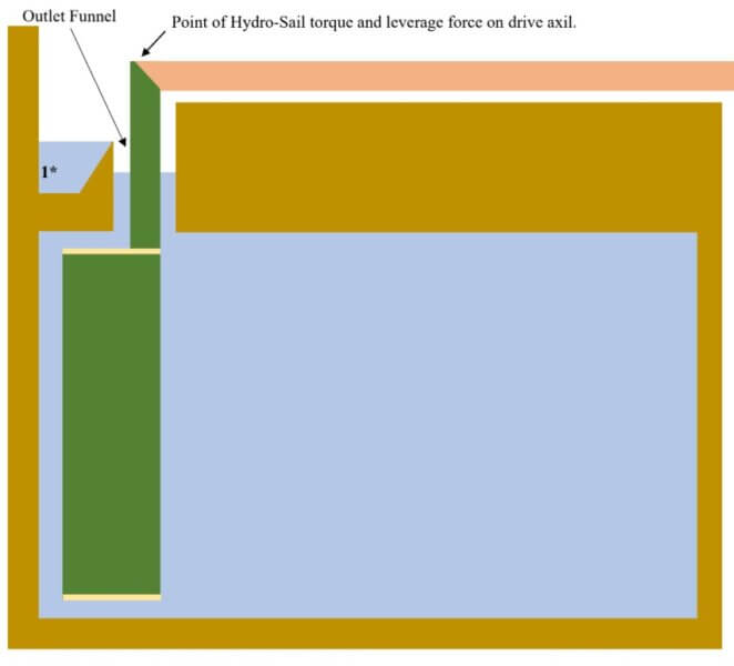
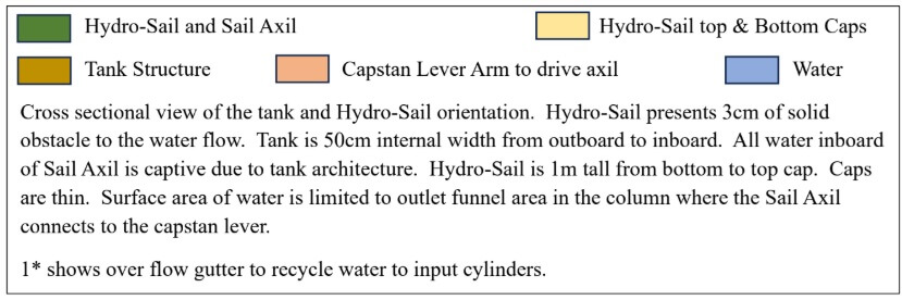
Captive Water Flow and Energy Channeling
Due to the architecture of the tank presenting a small surface area to the atmosphere, the water flow is captive. The energy is also channeled, like a waveguide. There is a set cubic volume, with a set quantity of water molecules. Water mass cannot use the surface area to absorb movement and turbulence. If the surface area in one spot rises, the surface area of the rest of the outlet funnel will fall to accommodate the turbulence.
The water molecules in the captive channel can only shift in location. And the spot that it shifts from has to be filled by water already near that area. The Hydro-Sail as an obstruction causes this shift in mass location (mass in motion). Currents form. Water molecules will shift but can’t separate from each other. They have to shift where the energy load paths are created.
Energy Behavior and Pressure Equalization
Energy has to shift as well. It does it in accordance with the characteristics of energy, not water. It happens really really fast. Physicists call it Pressure Equalization. Pressure is a measure of the total energy in a space. Maybe more about that later.
The operational architecture of solid, liquid, and energy environments requires nature to manifest several physical phenomena, one on top of the other, in the physics cloud that is stable around the Hydro-Sail as it travels around the doughnut river. This operational architecture is new technology.
Hydro-Sail and the Purpose of the Concept
Below I will go into some details about the Hydro-Sail, the other new technology in this discussion. Right now, I will stick to the purpose of this discussion. Hydro-Sail discussion is all about how much electricity will be coming out on the wire from the Higgins Engine—not about if there is electricity coming out.
The physics gets very deep. I will only give you a hint of how deep with the description of the Hydro-Sail. But this discussion is about a Proof of Concept. Electricity will come out, with only gravity going in.
Step-by-Step Mechanics of Energy Injection
The Drive Subsystem uses a dead weight (#1) free dropped a specific distance (#2), generating specific kinetic energy to strike the stop attached to the inner wheel (#3), causing a 1 cm jerk of the inner wheel. This inner wheel jerk rotation jerks the outer wheel 5 cm, driving the piston 5 cm (#4) in the drive cylinder.
Basic Math Behind the Energy Shot
For those of you that want to do some math: Pick an elevation that you want the dead weight to fall from. That will give you a velocity for that mass after time in freefall. Kinetic energy.
Figure out the time it will then take the mass to travel one centimeter at that velocity. The jerk wheel stop will travel one centimeter in that time. That will be the time it will take the outer wheel to drive the piston to travel five centimeters.
This multiplied velocity with 25 grams of water now gives you the total energy that is pumped into the Doughnut River with each shot.
Firing Rate and Energy Build-Up
If the Reset takes 15 seconds, each cylinder will fire four times a minute. Five cylinders equal 20 shots a minute. Times 60 is 1,200 shots an hour. After that, it is all about human design efficiency of the hardware. Thirty cylinders result in 7,200 input shots per hour. A large range is available for the engineering.
Final Energy Output and Conclusion
The total energy that is injected into the Doughnut River, and the efficiency of the hardware including the generator, determines the Watt Hours of electricity that comes out of the Higgins Engine. Remember, that output ultimately comes from gravity.
Bottom line, the Doughnut River will be running fast. A large volume of water weighs a lot. High mass in fast motion equals impressive energy storage.

Conceptual Functionality of the Higgins Engine
This should give you a fair picture of the conceptual functionality of the Higgins Engine. New technology, the Hydro-Sail, and the operational environment produce pollution-free electricity. Thank you, Nature, for the energy to operate our machinery. Sorry for the snub to your sunshine, rain, and wind. And given that you would have to be awfully pissed to hold back the tides on us, thank you.
Standalone Reset Subsystem and Its Operation
The standalone Reset Subsystem is driven by the energy harvested from the gravity of the Moon. It resets the mechanical parts and assemblies of the Drive Subsystem to their start position. Mechanical control provides for the automatic trigger that starts the Drive functionality.
The Drive Subsystem and Energy Harvesting
The standalone Drive Subsystem is driven by the energy harvested from the gravity of the Earth. It creates a flowing river that turns a paddle wheel which powers an electric generator. Nothing (from us) in, electricity (for us) out. I offer this as Proof of Concept for the Higgins Engine.
Hydro-Sail and Its Functionality
All up to now would still be true even if the Hydro-Sail were just a flat paddle. It isn’t.
For the following conceptual diagram, I am using dimensions and areas and volumes, etc. The physics cloud that appears around the Hydro-Sail is complex and a challenge to the PhDs I discussed this with, I might add.
I won’t go into that here. I’ll just try to list enough to provide understanding of the complexity. To me, the fact of that sheer complexity, from such a simple architecture, supports the claim of “new”. Research on current technology also supports “new”.
Physical Description of the Hydro-Sail
The Hydro-Sail is a 100 cm tall by 10 cm wide flat solid surface on one side. The front side, the Face. The back side of the sail is flat, then sharply cornered, then contoured sloped, then flat sloped.
The water flowing past the sail is split as it reaches the sail. A 4 cm by 100 cm area of the river’s cross-section is directed across the front of the sail. The remaining 46 cm wide by 100 cm deep river is directed across the backside of the sail.
Different Flow Characteristics on Each Side of the Sail
The rides down each side of the sail are very different from each other.
Water Flow and Pressure Interaction with the Sail
River flow against the outboard wall will come up to a 3 cm by 100 cm cross-section solid obstruction.
The water will flow past the trailing point of the sail, and immediately be under increasing pressure, due to the angled position of the sail with respect to the wall, for 10 cm by 100 cm of contact with the Face of the sail.
In the tank, H2O molecules have to escape confinement, be compressed, or adjust their location accordingly. Only so much space and so many molecules in this operational environment.
The water entering this area between the wall and the sail will escape over, under, and out the 1 cm gap at the front of the sail as it continues to flow with the vast majority of unobstructed captive water in the river flow.
Torque Generation from the Sail Face
All that water at velocity is very strong and keeps the disturbed water in line and pretty much up to speed. Meanwhile, the Hydro-Sail is dragging the capstan arm.
Every point of the Face 10x100 surface has a force vector pushing on it. Due to the positioning of the sail at an angle, each of those points are a separate torque wrench.
There is mechanical advantage from each point to the sail axil. A mechanical advantage gradient along the 10 cm width.
But each point all along that torque wrench is additive to the torque total applied to the axil of the sail. For 100 cm tall to be combined as one torque force on the load point for the capstan arm.
This is one source of force from the Face of the sail—mechanically advantaged torque.
Leverage Force from the Sail Length
Another force applied to the capstan from the Hydro-Sail is good old-fashioned leverage. Good old-fashioned mechanical physics.
A flat paddle (your father's paddle wheel) only provides leverage to the wheel. The torque force is one advantage the Hydro-Sail provides over a flat paddle.
The sail is 100 cm tall. It is attached to the capstan arm at the top end. The other end is hanging free. At every point on the axil there will be a force vector pushing on the axil (mass in motion coming in contact with a solid obstacle).
Which means that the bottom end of the sail axil will tend to bend forward and lead (drag) the capstan arm around the tank.
Which means that the sail is a straight mechanical lever on the capstan arm with a gradient of mechanical advantage depending on the distance from any given point to the capstan connection.
All of those force vectors along the axil are additive for the total forward leverage force applied to the capstan.
Addition of all the torque force and the leverage force are concentrated at the end point on the capstan arm. Pointing in the direction we want to go.
Backside Water Dynamics and Energy Shift
The backside of the sail creates a different environment and different forces applied to the Hydro-Sail. The vast majority of water in the tank is flowing unobstructed.
This free-flowing water reaches the sail and the overwhelming majority of it remains unobstructed, by a solid. However, the angular positioning of the sail and the shape of the backside creates a different obstacle.
Imagine, you are a water molecule rushing along beside another molecule at about 10 km/hr. All of a sudden, your neighbor disappears and you are up against a solid wall, still at accelerating angular velocity.
Centrifugal force physics applies here. And then the floor drops out from under you, and continues to drop away for 10 more centimeters of forward distance.
Spiral Flow and Pressure Equalization
This is a new expanding captive zone being created that must be filled, with the limited number of water molecules available in the captive channel.
At the point where the floor drops, you are going to go tumbling. And the water molecules on your inboard side will try to fill in the spot where you were just taking up.
But the captive environment will not just let water fill in, because someone has to fill in behind them, etc., all the way around the tank.
And remember that there are water molecules being compressed on the front side of the sail, and flooding in above and below the sail to your side.
Basically, there will be a shift in location of the water, as it flows forward, from the Face to the Backside of the Hydro-Sail. Because of the water flow direction, the trajectory of the water molecule will be a spiral along the river path.
Energy Load Paths and Eddy Lift
The shifting of the water in motion is due to the Pressure Equalization of the energy. A Fluid Mechanics set of physics.
A high-pressure zone is created on the Face, and a low-pressure zone is created on the backside. Energy will homogenize in a captive environment, very quickly. Around 600 km/hr.
Energy load paths are created starting in the high-pressure zone and extending to the low-pressure zone, around the sail.
Water will be directed (shifted) depending on the energy load paths. As the energy equalizes around the sail, currents and turmoil will ensue.
The backside of the sail will see eddies and vortexes manifest on its surface. It may even look like two tornadoes lying horizontally, one on top of the other, with counter-rotating open maws facing downstream. There may be some Von Karman Vortices theory here.
In any case, eddies will be formed and that brings Eddie Lift into play. Eddie lift is responsible for keeping the F-117 fighter jet aloft—not lift from wings.
Any Eddie lift will be a force vector extending away from the backside of the sail (in the direction we want to go), and is another additive to the total forces experienced by the sail.
This establishes the boundaries of the Physics Cloud stabilized around the Hydro-Sail.
Hydro-Lift Possibility and Aerodynamic Analogy
The combination of the front and backside environments may also create forces that are additive to the total force the sail applies to the capstan arm.
In aerodynamics there are physics for aero-lift provided by an airfoil shape of an airplane wing.
That calculated lift is a measure of the amount of work that can be accomplished by the wing. How heavy is the fuselage of the plane that the wing can carry?
There are three main parameters for the calculation of aero-lift: 1) the air pressure under the wing; 2) the air pressure above the wing; and 3) the velocity of the air flowing across the wing.
The structure creates a high-pressure zone under the wing and a low-pressure zone above the wing. The differential between the two zones is used to determine the lift.
The actual air pressure under the wing does not support the load of the airplane. How high is the air pressure at 30,000 feet, where airplanes fly?
Anyway, it is the environment that I am referring to. A solid structure separating differing pressure zones, with the environmental medium flowing across it.
The Hydro-Sail is a solid structure separating differing pressure zones, with the environmental medium flowing across it. Could there be Hydro-Lift here? It would be another additive to the total forces experienced by the sail.
Other Phenomena: Resonance and Suction Force
There are other physical phenomena that may manifest within the cloud. For instance, there may be Acoustic Resonance Amplification.
Simply (not technically) explained, this is when two pulses come together and the resulting pulse contains more energy than the straight addition of the two individual waves.
It has to do with the frequency of the energy matching up with the frequency of the medium the energy is propagating through.
There is a lot more to this. But scientists have set up test rigs that allow them to measure the phenomenon. The test rig shape includes a corner in the channel where this behavior happens. The Hydro-Sail has a cap on the top and bottom. The corners where the caps meet the sail may provide the same setup.
And here is one for the real dreamers. At the end of the sail, when two different energy and water environments slam together (front and back sides), because the sail no longer separates them, there will be turmoil.
Again, maybe some Von Karman Vortices. The result may be that the water environment in front of the sail may be “easier” to push a solid through than “organized” water flow.
That would mean less friction from the solid sail on the forward flow of water and a slower decrease in the velocity of the water.
The sail seems to exhibit less drag on the river. More load carrying capability of the sail at the same angular velocity around the doughnut.
And if you are really reaching, maybe there is an area right on the upstream edge of the sail where “Suction Force” is manifest to drag the solid into the area where there is a void created by the two different local environments trying to slam together, just past the edge.
Suction Force—the answer to the Dark Energy question. Hey, I said “really reaching”.
Conclusion: A New Physics Cloud
I’ll hold off here. As a figure of merit, the sample of physics that I have presented represents many whiteboards full of math. The whole physics story would be more whiteboards than you would want to see.
This should give you a bit of an understanding about the physics internal to the physics cloud. I had mentioned before that it was challenging to PhDs that I have met with.
One told me that modeling the physics cloud was beyond him. I needed a specialist.
Modeling, in physics, means describing everything, and how those things interact, using the language of mathematics.
The physics surrounding the Hydro-Sail, in its described operating environment, metaphorically is a new recipe for cookie dough. A totally new combination of ingredients for the dough. A totally new cookie. A new physics cloud.
That is why I claim that the Higgins Engine, with the Hydro-Sail, could be a giant leap over the use of a flat paddle for a water wheel.
But again, this part of the discussion is about “how much”, not “if” there will be electricity coming out. There is total agreement that there will be electricity coming out.
Final Words on the Higgins Engine
The Higgins Engine is new technology to harvest energy from gravity, and process that energy to produce electricity.
The operation of the engine is pollution free. The structure and architecture of the engine are straightforward mechanical design. No additional power input is required beyond the gravity provided by the Moon and the Earth.
Electricity comes out, with only gravity going in. I rest my case.
Any other new ideas about how to provide the energy we will need to power the new machines that must come? The more ideas out there, the better the chance some will work. This is only one new one.