A buck converter is a type of switching regulator which we use to step down a high DC voltage to a lower DC voltage. The inductor is a very important part of the circuit because it stores and releases energy to keep output power almost same as input power. This is biggest advantage of a buck converter.
Meaning while a buck converter steps down a high voltage to a desired lower output voltage, it proportionately increases the current, depending on how much voltage has been reduced at the output.
This results in retention of input power and minimized heat dissipation and overall high working efficiency.
Buck Converter Inductor Calculator
Enter the values below to calculate the optimal inductor value based on your desired ripple current.
Results:
Duty Cycle: 0 %
Optimal Inductor Value: 0 µH
What Does the Inductor Do in a Buck Converter?
The inductor helps in many ways:
- It smoothes out the output current so it does not jump around too much.
- It stores energy when the switch is ON and releases energy when the switch is OFF.
- It reduces ripple current which helps the output stay steady and makes the converter more stable.
How the Inductor Works in a Buck Converter
When the MOSFET switch is ON:
- The inductor stores energy from the input supply.
- The current in the inductor increases slowly.
- The voltage across the inductor is:
V_L = V_in - V_out
When the MOSFET switch is OFF:
- The inductor releases its stored energy to the output.
- The current through the inductor decreases slowly.
- The voltage across the inductor is:
V_L = -V_out
This happens again and again at the switching frequency. In the end the output becomes a steady DC voltage.
How to Calculate the Inductor for a Buck Converter
Now, to calculate the inductor value (L), we use the following formula:
L = (V_in - V_out) * D / (Δ I_L * f)
Where:
- L is the inductor value in Henrys (H).
- V_in is the input voltage (V).
- V_out is the output voltage (V).
- D is the duty cycle and is given by:
D = V_out / V_in - Δ I_L is the ripple current (A).
- f is the switching frequency (Hz).
What is Ripple Current?
Now the ripple current is a small variation in the current which is usually set as 30% of the output current. So, if the output current is 2A, then the ripple current (Δ I_L) will be:
Δ I_L = 0.3 * I_out
So for a 2A output current, the ripple current would be 0.6A. The ripple current affects how big the inductor needs to be. Larger ripple current means we can use a smaller inductor but it causes more noise and losses. On the other hand, smaller ripple current needs a larger inductor but the converter is more stable. The 30% rule is a good balance between size and performance.
Duty Cycle
The duty cycle is how long the MOSFET switch stays ON during each cycle, and it depends on the ratio of Vout to Vin. We calculate it like this:
D = V_out / V_in
If the duty cycle is too high, the switch will be ON for a longer time, giving more energy to the load. If it’s low, the switch will be ON for less time.
Example Calculation
Now let us say we have:
- V_in = 12V
- V_out = 5V
- f = 100kHz
- I_out = 2A
- Ripple current (Δ I_L) = 30% of 2A = 0.6A
Now we calculate the duty cycle first:
D = 5 / 12 = 0.416
Now we can calculate the inductor:
L = (12 - 5) * 0.416 / (0.6 * 100000)
L = 7 * 0.416 / 60000
L = 2.91 / 60000 = 48.5µH
So for this setup the inductor value is 48.5 µH.
Summary:
- A buck converter transforms a high voltage input into the required low voltage output with high efficiency which ensures minimum losses by retaining the output power as close as possible to the input power.
- The inductor value relies on the input voltage, output voltage, switching frequency and ripple current.
- If you use a higher switching frequency then you can get away with a smaller inductor but it may cause more switching losses.
- A 30% ripple current is a good choice because it gives a good balance between efficiency and performance.
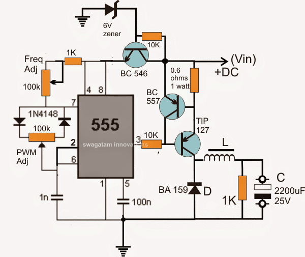
Example of a high Voltage Buck Converter
