In this article I have explained a simple RF remote control circuit which can be used for activating a digital camera remotely, by a press of a button. The idea was requested by Mr. Pat
Circuit Objectives and Requirements
- I'm Pat, from France. Congratulations for your blog & website about electronic's devices : it's the paradise :o)
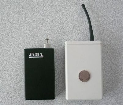
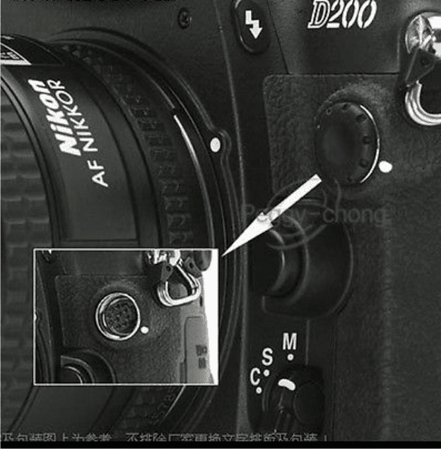
- I'm photographer & i'm looking for a simple remote control for my Nikon D200 in RF. I need a transmitter and receiver in a single radio frequencies with good reach and operate on a 9V battery. the goal is to trigger the camera remotely. The Nikon camera has a 10-pin socket designed for it.
- Here's a business model but very expensive here :
Would you have an assembly to propose? (I tinker with classical electronics as ham radio... :o)
thanks for your help :o)
Patrick / F5CEY
~90 miles north of Paris
France

Analyzing the Circuit
Hi Pat,
I am glad you liked my website.
I'll to try post the design as per my analysis soon in my website.
In the meantime you can go through the following article which I would be
using for the proposed implementation.
https://www.homemade-circuits.com/2013/07/simple-100-meter-rf-module-remote.html
The Design
I have discussed a simple 433 MHz RF remote control module based circuits which can be used in all kinds of remote switching applications within a range of 100 meters. Other forms of modules can be employed for getting higher ranges of distance.
These RF remote control modules can be also effectively used for the discussed remote camera switching application.
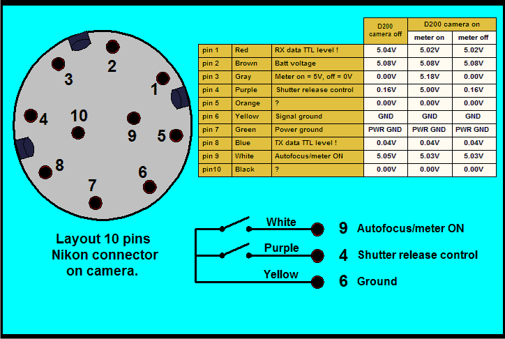
As per my interpretation, the pinouts from the camera's 10 pin socket which are relevant to the remote switching of the camera (using the proposed RF modules) are as follows:
pin#1 = Rx input data (triggering pulse)
pin#2 = +5V external input, or from the camera battery
pin#7 = power ground to be integrated with the RF module ground or negative.
Other pinouts does not look relevant for the intended functions and therefore may be left open.
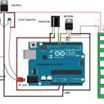
As per the above data, the Rx or receiver module output could be integrated with the camera's existing 10 pin connector in the following shown manner:
If the camera is intended to be operated with an external power source then an external battery may be utilized for powering the Rx module and the same may be fed to the camera via the pin#2 of its 10 pin socket.
If the internal battery of the camera is used which looks more appropriate then the Rx module could be powered from this source via the pin#2.
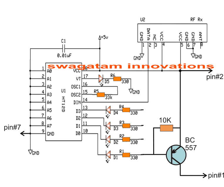
The BC557 can be seen configured with one of the output pinouts of the RX module which happens to be pin#10 from the decoder IC of the Rx module, although any of the other output could be used for the same results.
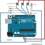
In the Tx module you will also find compatible 4 inputs with switches, each corresponding to the individual 4 outputs of the Rx module, meaning if pin#10 button of the Tx is pressed, this will activate the pin#10 of the Rx module.... and so on.
Therefore in the above case the pin#10 switch of the Tx needs to be pressed for implementing the required remote controlled camera switching.
The press of a button in the Tx handset is supposed to generate a low logic at the relevant pinout of the Rx module (pin#10 in the present case), which causes the BBC557 to activate and send a +5V TTL pulse to pin#1 of the camera, activating the camera shutters.
The Transmitter circuit for the proposed remote control camera switching circuit
The following circuit depicts the transmitter circuit or the Tx circuit stage which is supposed to be utilized for triggering the camera located in the remote location:
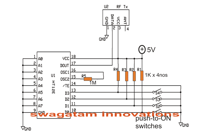
As can be seen in the above image, the four switches correspond to the respective 4 outputs of the Rx module.
However since pin#10 is employed in the present design, the switch associated with pin#10 should be used which is indicated as SW1 in the above diagram. The rest of the switches could be ignored.

Comments
Hi again,
I tried the 1N4148 as suggested but no difference. It will invert properly, switching off when an incoming signal is detected, but when an incoming signal comes, the LED just goes extra bright…
try a pull down resistor across base emitter of the BJT, use a value that just corrects this issue.
or you can also try an opamp in the comparator mode for the detection
I am getting perfect switching with a 2.2k resistor on a different input that is 0.8v, but not the 3.3v…
Thanks,
I have tried the diagram shown below
https://www.homemade-circuits.com/wp-content/uploads/2018/04/pull-up-transistor.jpg
and have tried a variety of resistors in conjunction with a BC547. I am not getting clean switching on an input of 3.3v and am wondering what I am doing wrong. I have tried a variety of different configurations but nothing switches cleanly. How do I figure out what to use?
Thanks
try using a 1N4148 diode at the base of the transistor….
Hi Swag,
I have a really simple request. I have made a simple 38khz break-beam sensor but need to make an inverted output selectable with a switch so I can choose to switch between the output and inverted output for different uses.
Any help greatly appreciated as always
Thanks
Hi Nathan, you can simply do it by attaching a NPN BJT stage with the output of the circuit. The collector of the BJT can be connected with a pull up resistor to the positive supply, and emitter with the ground.
A switch may be configured to select this collector of the BJT or the output from the circuit directly…this will allow you to select between the normal output or the inverted output…
Hi Swagatan, happy new year. I am Okey Onah from Nigeria. Please, I have some Ucom Cameras ( web cameras ) in my junk box which are working perfectly but I don’t have laptop or desktop in my home. My question is, ” can I use the Ucom cameras with my Plasma TV to achieve a room monitor or a security which will be displaying on the TV screen through the help of the Camera?”. If yes, help me with the connection procedures and circuit schematics involve in achieving this goal. Thank you so kindly for being there for people like me because I have achieved and learnt alot from your website. I wish to hearing from you soon.
Happy New Year Okey,
I am really sorry I have no idea regrading the question that you have asked, so I won’t be able to suggest much on this…