
In this article we are going to learn many interesting SCR application circuits and also learn the main features and properties of an SCR also called a thyristor device.
What's an SCR or Thyristor
SCR is the acronym of Silicon Controlled Rectifier, as the name suggests it's a kind of diode or a rectifying agent whose conduction or operation can be controlled through an external trigger.
It means that this device will switch ON or OFF in response to an external small signal or voltage, quite similar to a transistor, yet hugely different with its technical characteristics.
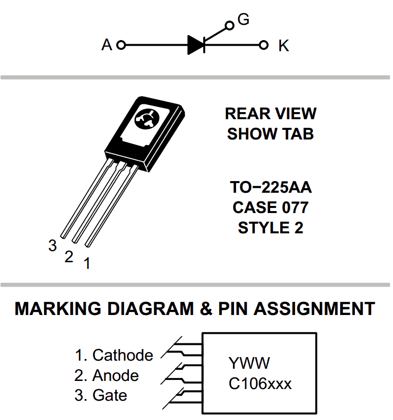
SCR C106 pinouts
Looking at the figure we can see that a SCR has three leads which mat be identified as follows:
Keeping the printed side of the device facing us,
- The right end lead is called the "gate".
- The center lead is the "Anode", and
- The left end lead is the "Cathode"

How to Connect an SCR
The gate is the trigger input of an SCR and requires a DC trigger with a voltage of around 2 volts, the DC should be ideally more than 10mA. This trigger is applied across the gate and the ground of the circuit, meaning the positive of the DC goes to the gate and the negative to the ground.
The conduction of voltage across the anode and the cathode is switched ON when the gate trigger is applied and vice versa.
The extreme left lead or the cathode of an SCR should always be connected to the ground of the triggering circuit, meaning the ground of the triggering circuit should be made common by connecting to the SCR cathode or else the SCR will never respond to the applied triggers.
The load is always connected across the anode and an AC supply voltage which may be required for activating the load.
SCRs are specifically suited for switching AC loads or pulsed DC loads. Pure, or clean DC loads will not work with SCRs, since the DC will cause a latching effect on the SCR and will not allow to switch OFF even after the gate trigger is removed.
SCR Application Circuits
In this part, we will look at some of the popular applications of SCR which are in the form of static switch, a phase-control network, SCR battery charger, temperature controller, and a single-source emergency-lighting
system.
Series-Static-Switch
A half-wave series static switch can be witnessed in the following figure. When the switch is pressed to allow the supply in, current at the gate of the SCR becomes active during the positive cycle of the input signal, switching ON the SCR.
Resistor R1 controls and restricts the amount of gate current.
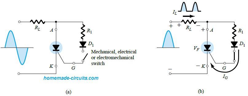
In the switched ON condition the anode to cathode voltage VF of the SCR decreases to the level of the conduction value of RL. This causes the gate current to reduce drastically, and minimum loss at the gate circuitry.
During the negative input cycle, the SCR is switched OFF, because of the anode getting more negative than the cathode. Diode D1 safeguards the SCR from a reversal of the gate current.
The right side section of the above image shows the resulting waveform for the load current and the voltage. The waveform looks like a half-wave supply across the load.
Closing the switch allows the user to achieve a conduction level lower than 180 degrees at phase displacements happening during the positive period of the input AC signal.
For achieving conduction angles between 90° and 180°, the following circuit can be used. This design is similar to the above, except the resistor, which is in the form of the variable resistor here, and the manual switch is eliminated.
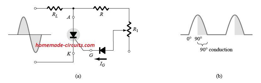
The network using R and R1 ensures a properly controlled gate current for the SCR during the positive half cycle of the input AC.
Moving the variable resistor R1 slider arm to maximum, or towards the lower most point, the gate current may become too weak to reach the gate of the SCR, and this will never allow the SCR to switch ON.
On the other hand when it is moved upwards, the gate current will slowly increase until the SCR turn ON magnitude is reached. Thus, using the variable resistor the user is able to set the level of the turn ON current for the SCR anywhere between 0° and 90°, as indicated at the right hand side of the above diagram.
For the R1 value, if it's rather low, will cause the SCR to fire quickly, leading to the a similar outcome obtained from the first figure above (180° conduction).
However, if the R1 value is bigger, a higher positive input voltage will be needed to fire the SCR. This situation wouldn't allow us to extend the control over 90° phase displacement, since the input is at its highest level at this point.
If the SCR is unable to fire at this level or for the lower values of the input voltages at the positive slope of the AC cycle, the response will be exactly the same for the negative slopes of the input cycle.
Technically, this type of working of an SCR is called half-wave variable-resistance phase control.
This method can be effectively used in applications requiring RMS current control or load power control.
Battery Charger using SCR
Another very popular application of the SCR is in the form of battery charger controllers.
A basic design of an SCR based battery charger can be seen in the following diagram. The shaded portion will be our main area of discussion.
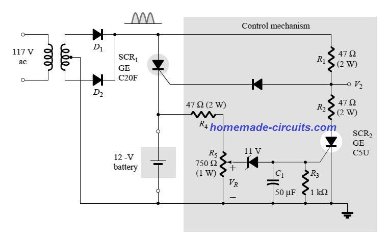
Parts List
- Resistors
- 47 Ohm 2 Watt = 3
- 1k 1/4 watt 5% = 1
- Preset 750 Ohms 1 watt = 1
- Capacitor
- 50 uF / 50 V = 1
- SCR1 = any 15 amp 200 V SCR = 1
- SCR2 = C106 = 1
- SCR1 gate diode = 1N4007 = 1
- Transformer Diodes = 15 amp 200 V = 2
- Transformer rating as per battery spec. = 1
The working of the above SCR controlled battery charger can be understood with the following explanation:
The input stepped down AC is full wave rectified through the diodes D1, D2 and supplied across the SCR anode/cathode terminals. The battery which is under charging can be seen in series with the cathode terminal.
When the battery is in the discharged condition, its voltage is low enough to keep the SCR2 is the switched OFF state. Due to the open state of SCR2, the SCR1 control circuit behaves exactly like our series static switch discussed in the previous paragraphs.
With the input rectified supply adequately rated, triggers ON the SCR1 with a gate current that's regulated by R1.
This instantly turns ON the SCR and the battery begins charging via the anode/cathode SCR conduction.
In the beginning, due to the low discharged level of the battery, the VR will have a lower potential as set by the R5 preset or potential divider.
At this point the VR level will be too low to turn ON the 11 V zener diode. In its non-conducting state the zener will be almost like an open circuit, causing the SCR2 to be completely switched OFF, due to virtually zero gate current.
Also, the presence of C1 ensures that the SCR2 is never accidentally turned ON due to voltage transients or spikes.
As the battery charges, its terminal voltage gradually rises, and ultimately when it reaches the set full charge value, VR becomes just sufficient to turn ON the 11 V zener diode, subsequently firing ON the SCR2.
As soon as SCR2 fires, it effectively generates a short circuit, connecting R2 end terminal to ground, and enabling the potential divider created by R1, R2 network at the gate of the SCR1.
The activation of the R1/R2 potential divider at the gate of SCR1 causes an instant drop in the gate current current of SCR1, forcing it to shut off.
This results in the supply to the battery getting cut off, ensuring the battery is not allowed to over charge.
After this, if the battery voltage tends to drop below the preset value, the 11 V zener switches OFF, causing SCR1 to switch ON yet again to repeat the charging cycle.
AC Heater Control using SCR
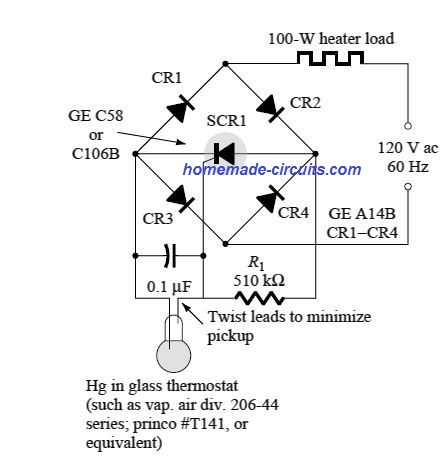
The above diagram shows a classic heater control application using an SCR.
The circuit is designed to switch ON and OFF the 100 watt heater depending on the thermostat switching.
A mercury-in-glass thermostat is used here, which are supposed to be extremely sensitive to the changes in the temperature levels surrounding it.
To be precise it can sense even a change of a 0.1°C temperatures.
However, since these types of thermostats are normally rated to handle very small magnitudes of current in the range of 1 mA or so, and therefore it is not too popular in temperature control circuits.
In the discussed heater control application, the SCR is used as a current amplifier for amplifying the thermostat current.
Actually, the SCR does not function like a traditional amplifier, rather as a current sensor, which allows the varying thermostat characteristics to control the higher current level switching of the SCR.
We can see that the supply to the SCR is applied through the heater and a full bridge rectifier, which allows a full wave rectified DC supply for the SCR.
During the period, when the thermostat is in the open state, the potential across the 0.1uF capacitor is charged to the firing level of the SCR gate potential via pulses generated by each rectified DC pulse.
The time constant for charging the capacitor is established by the product of the RC elements.
This enables the SCR to conduct during these pulsed DC half cycle triggers, allowing the current to pass through the heater, and allow the required heating process.
As the heater heats up and it temperature rises, at the predetermined point, causes the conductive thermostat to activate and create a short circuit across the 0.1uF capacitor. This in turn switches OFF the SCR and cuts off power to the heater, causing its temperature to drop gradually, until it drops to a level where the thermostat yet again is disabled and the SCR fires ON.
Emergency Lamp using SCR
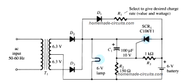
The next SCR application talks about a single-source emergency lamp design in which a 6 V battery is kept in a topped up charged condition, so that the connected lamp can be seamlessly switched ON whenever a power failure happens.
When power is available, a full wave rectified DC supply using D1, D2 reaches the connected 6 V lamp.
C1 is allowed to charge to a level that's slightly lower than the difference between the peak DC of the fully rectified supply and the voltage across R2, as determined by the supply input and charge level of the 6 V battery.
Under any circumstances, the cathode potential level of the SCR is help higher than its anode, and also gate to cathode voltage is held negative. This make sure that the SCR stays in the non-conducting state.
The charging rate of the attached battery is determined by R1, and enabled through the diode D1.
The charging is sustained only as long a the D1 anode remains more positive than its cathode.
While the input power is present, the full wave rectified across the emergency lamp keeps it switched ON.
During power failure situation, the capacitor C1 begins discharging through D1, R1, and R3, until the point where the SCR1 cathode becomes less positive than its cathode.
Also, meanwhile the R2, R3, junction goes positive resulting in an increased gate to cathode voltage for the SCR, turning it ON.
The SCR now fires and allows the battery to get connected with the lamp, instantly illuminating it through battery power.
The lamp is allowed to stay in the illuminated state as if nothing had happened.
When power returns, the capacitors C1 is yet again recharged, causing the SCR to switch OFF, and cutting off the battery power to the lamp, so that the lamp now illuminates through the input DC supply.
Miscellaneous SCR Applications Collected from this Website
Simple Rain Alarm:
The above circuit of a rain alarm can be used for activating a AC load, like a lamp or an automatic folding cover or shade.
The sensor is made by placing to metallic pegs, or screws or similar metal over a plastic body. The wires from these metals are connected across the base of a triggering transistor stage.
The sensor is the only part of the circuit which is placed outdoors, for sensing a rain fall.
When a rain fall begins, water droplets bridge the metals of the sensor.
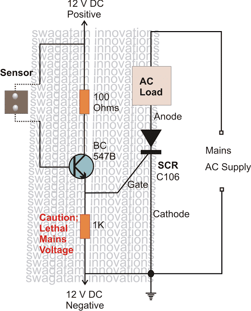
Small voltage start leaking across the sensor metals and reach the base of the transistor, the transistor immediately conducts and supplies the required gate current to the SCR.
The SCR also responds and switches ON the connected AC load for pulling an automatic cover or simply an alarm for correcting the situation as desired by the user.
SCR Burglar Alarm
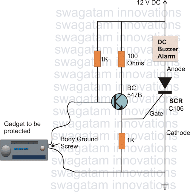
We discussed in the previous section regarding a special property of SCR where it latches in response to DC loads.
The circuit described below exploits the above property of the SCR effectively for triggering an alarm in response to a possible theft.
Here, initially the SCR is held in a switched OFF position as long as its gate stays rigged or screwed with the ground potential which happens to be the body of the asset which is required to be protected.
If an attempt to steal the asset is made by unscrewing the relevant bolt, the ground potential to the SCR is removed and the transistor gets activated through the associated resistor connected across its base and positive.
The SCR also instantly triggers because now it gets its gate voltage from the transistor emitter, and latches sounding the connected DC alarm.
The alarm remains switched ON until its switched OFF manually, hopefully by the actual owner.
SCR Latch Circuit
The following diagram shows a simple latch circuit using SCR, resistors, LED and a push button.
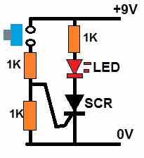
Initially when power is applied the SCR remains switched OFF and the LED remains shut off. As soon as the push button is pressed, the supply DC reaches the SCR gate and turns it ON.
Once switched ON, the SCR instantly latches itself and turns ON the LED permanently. The SCR and the LED remains latched ON even after the push button is released.
The only way to turn of the SCR/LED and reset the circuit is to short circuit the SCR anode/cathode pins momentarily or switch OFF and ON the 9 V power DC input.
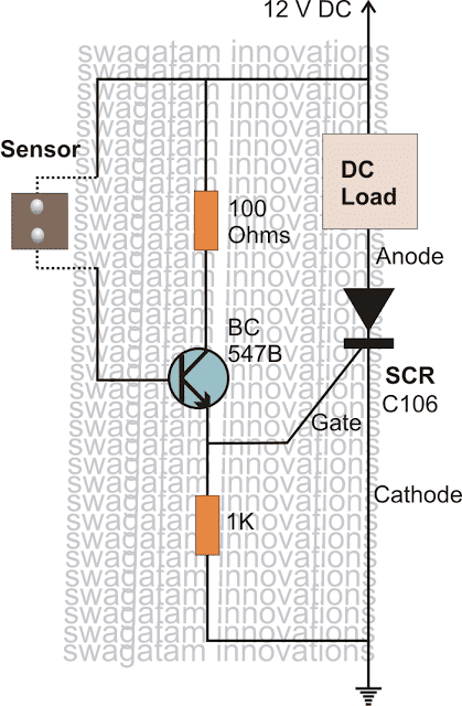
SCR Over Temperature Indicator Circuit
The following circuit shows a how an SCR can be used to latch ON and indicate an over temperature condition through an LED.
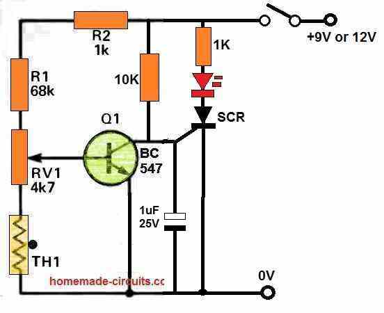
The preset is so adjusted that the transistor Q1 remains switched ON when power is first switched ON.
Q1 being switched ON via R1 and R2, the SCR gate remains grounded and the SCR is unable to turn ON.
Now, as the temperature on the thermistor begins rising, its resistance begins decreasing. At a specific threshold, depending on the RV1 setting, the thermistor resistance becomes small enough to cause significant drop on the base bias of Q1, causing Q1 to shut down.
As soon as Q1 shuts down, the SCR is able to get the triggering voltage via the 10K resistor and it instantly turns ON, which is in turn switches ON the LED, indicating an over temperature.
SCR Drill Speed Controller Circuit
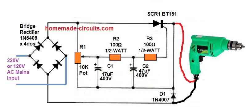
The figure above shows how a simple yet effective AC 220 V drill speed controller circuit can be built using an SCR, a bridge rectifier, few resistors and a potentiometer.
As the potentiometer is adjusted, it adjusts the firing or the triggering range of the SCR. For every half DC pulse wave the SCR is able to conduct only for that much time which is determined by the adjustment of the R1 pot.
When the R1 slider is adjusted higher on the positive side it causes the SCR to trigger more frequently causing the drill machine to remain switched ON for longer periods of the half wave cycles and the drill speed increases.
When the R1 slider is moved lower towards the ground line, exactly opposite happens causing the drill speed to decrease.
Automatic Porch Light Circuit using SCR
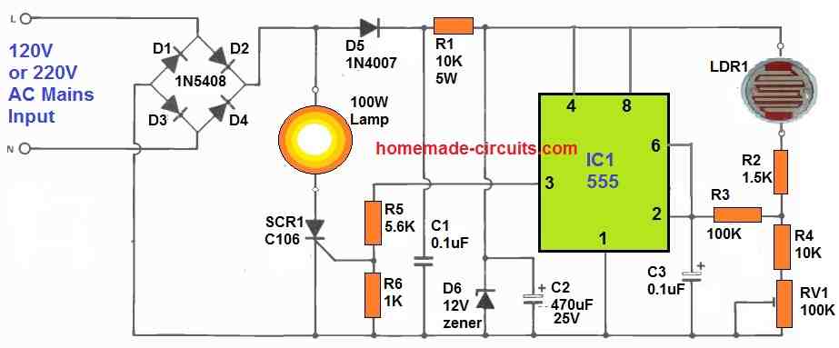
Another simple SCR application could be as shown in the figure above, which is an automatic porch light circuit. Here the IC 555 is used as a comparator circuit which detects the voltage level from the LDR.
During day time when the resistance of the LDR is low, causes more voltage to reach the pin#2 of the IC 555 via the LDR.
This causes the output of the IC 555 to remain at logic zero, diaabling the gate of the SCR so that it remains switched OFF. As long as the SCR is switched OFF the attached lamp also remains switched OFF.
When darkness sets in, the LDR resistance increases causing the pin#2 of the IC 555 to drop significantly, until finally it reaches the ground level via the setting of RV1.
This allows the output pin#3 of the IC 555 to become high and supply the required DC trigger voltage for the SCR.
The SCR now switches ON and turns ON the attached lamp.
In this way the porch light automatically switches ON during dark or at night time and switches OFF automatically when day break sets in or during the day time.
Simple Fence Charger, Energizer Circuit
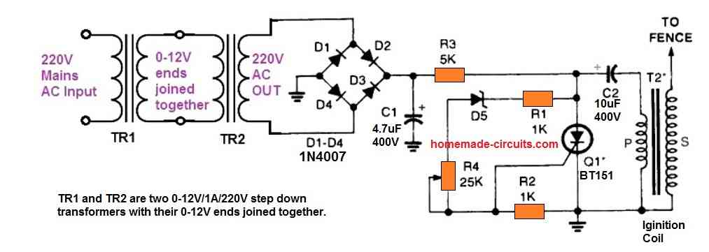
SCRs becomes ideally suited for making fence charger circuits. Fence chargers primarily require a high voltage generator stage, where a high switching device like an SCR becomes highly imperative. SCRs thus become specifically suitable for such applications where they are used for generating the required high arcing voltages.
SCR Power Supply Short Circuit Protection
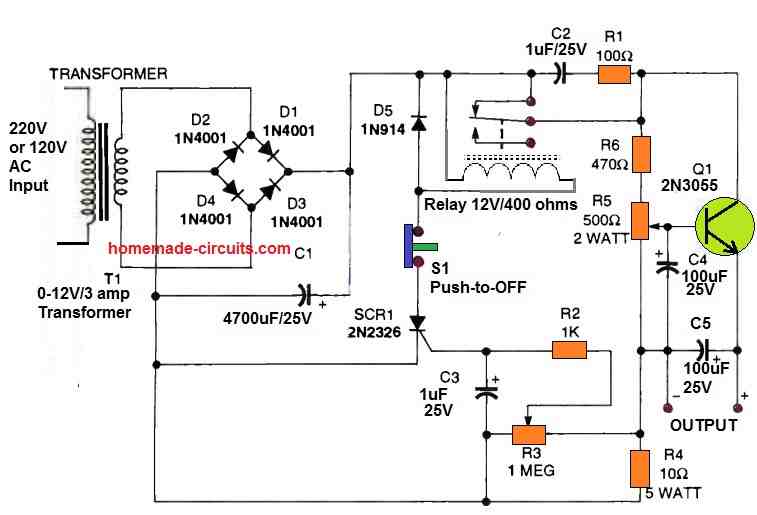
Another novel application of SCR is shown in the above figure as a short circuit protector for a power supply circuit.
The design also helps the power supply to protect it against overload or over current situations.
During an overload or an over current or a short circuit across the output, the voltage across R4 increases significantly until it is sufficient to trigger ON the SCR.
As soon the as the SCR is triggered ON, it latches and switches ON the relay.
The relay contacts which are wired with the power supply input voltage quickly moves towards the N/O contacts disconnecting the input supply from the pass transistor and the output, thus preventing the over current or short circuit condition at the output of the power supply.
CDI Circuit for Automobiles
As explained in the above application, SCRs are also widely used in automobiles, in their ignition systems. Capacitive discharge ignition circuits or CDI systems employ SCRs for generating high voltage switching required for the ignition process or for starting a vehicle ignition.
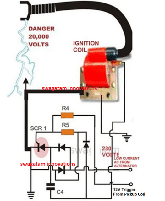
Parts List
R4 = 56 Ohms 1/2 watt
R5 = 100 Ohms, 1/2 watt
C4 = 1uF/250V, PPC
SCR = BT151 recommended.
All Diodes = 1N4007
Coil = Standard two-wheeler ignition Coil
Have Questions? Please Comment below to Solve your Queries! Comments must be Related to the above Topic!!