A timer circuit design which could be used for turning the position of the eggs in an incubator between predetermined intervals of time was requested to me by one of the keen readers of this blog, Mr. Eugene.
The requested circuit has been exclusively designed by me and published here,
Circuit Specifications
Let's hear the whole episode:
I'm raising chickens for derby and I have hen that is laying eggs. For the hen to continue laying eggs, I need to incubate the eggs. I have researched incubator designs and parts and I have already assembled a simple one. I have a digital 220V ac thermostat and in order to protect it, it will only have to drive a 220V relay. This one already worked well.
Now I have an additional info that the eggs have to be rotated or moved upside down 3 times a day in order for the eggs to hatch well. I am planning to make a rows of eggs holder chained or built together driven by a motor such as electric fan swing motor. Its strong and moves very slowly and I think its quite enough. This 220v ac motor will be driven by a 6v dc relay. Now I need a relay driver circuit and a timer circuit that wil trigger the relay driver more or less every 8 hours for approximately 3 seconds only.
I may not have enough words to reach 300 but I think my intention is clear enough. But if the blog requires 300 words, I will try to extend my explanation.
Thank yo very much and I hope you can help me.
Eugene"
Designing an Incubator Egg Timer Circuit
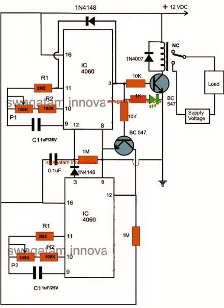
The circuit of the proposed incubator egg timer and optimizer is given below:P1 should be adjusted for the long 8 hour duration and P2 for the short 3 seconds duration.
Circuit simulation:
Looking at the circuit diagram we can see that it consists of two identical IC 4060 stages which are coupled across each other for implementing the proposed actions.
The upper timer stage is intended for producing long time intervals and therefore its output is taken from pin #3, while the lower IC generates smaller time intervals and so its pin #15 is chosen as the output.
When power is switched ON the following things happen with the circuit:
The 0.1uF capacitor resets the upper IC so that it can start counting, during this period its pin #3 is at logic low which keeps the relay driver stage switched OFF, also the lower BC547 is kept disabled, which keeps pin #12 of the lower IC at high logic which in turn renders the lower IC inactive.
After the predetermined period is lapsed, pin #3 of the upper IC goes high, this switches ON the relay driver stage and also the lower IC pin #12 gets reset, this toggles the lower IC into counting mode.
After the predetermined period, pin #15 of the lower IC becomes high, which sends a logic high to the reset pin #12 of the upper IC, resetting it back to its original position......the cycle repeats, and goes on repeating as long as power is available.
The lower section can be upgraded for generating higher time intervals at par with the upper section by replacing pin15 with pin3 as already done in the diagram below.
The relay contacts are wired up to the motor for shuffling the egg orientation.
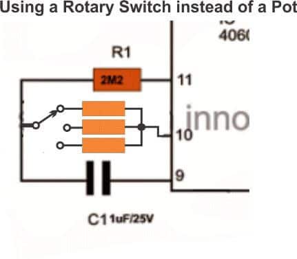
Using Rotary Switch for Adjusting the Time intervals
If you find adjusting the pot difficult and time consuming, you could easily replace them (P1, P2) with rotary switches as shown below. The involved could be also easily calculated with some quick and experimentation:


Comments
Hello Sir;
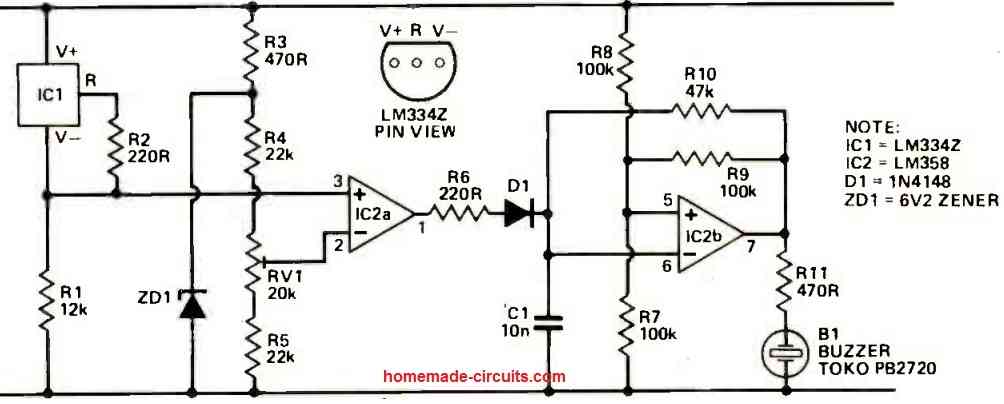
In line with hatched chicks, I would like to build make circular brooder house with an automatic temperature controller. Not using a microprocessor chip is it possible to design a temperature controller which will switch off when the temperature reaches a set high point and turn ON heaters when the temperature is below the set lower values?
Thanks in advance.
Hello Joseph,
You can try the second last circuit from the following article, which uses the IC LM35:
https://www.homemade-circuits.com/how-to-build-simple-electronic/
Hello Mr swag,
This is a good design , but my question is how can I interface a digital display to the circuit to read the predetermined time directly?
Thanks Yabagi, you can use the following circuit, and configure with the relay output of the timer
https://www.homemade-circuits.com/5-digit-frequency-counter-circuit/
the frequency input can be from a 1 second oscillator using IC 555….precision may not be critical
hi sir If possible I’ll try the circuits you shared.. Thanks
Thanks Rudrud, please do it and if possible provide a small video clips to my email.
Sir what caps i will ceramic or mylar caps?,.help me sir thanks
Sir the push button is for reseting purpose?,..because some time when i turn off the circuit and turn on again,the lower ic continues to count,..the upper ic not reseting properly,..
Ken, which push button are you referring to?
Sir i made the circuit and its working,.thanks for the design and the assistance sir,….
I am glad about it Ken, keep up the good work!
Sir when i connect led in pin#14 the blink is to slow sir,.what should i do sir to make the blink fast,..and does the capacitor in pin#9 affects the time interval,..how to compute ur desired time sir,.thanks
Try pin#7. Yes capacitor at pin#9 and resistor at pin#10 together are responsible for time delays or the frequency:
https://www.homemade-circuits.com/how-to-understand-ic-4060-pin-outs/
Sir if i remove the resistor P1 and P2,..what should b the initial time interval and the limit rotation of the motor?thanks sir ,..the circuit is working sir,.i just want to know the intial time so i can make a switch interval sir,.thanks sir swag
Please see the video in the following article, it will allow you to judge the approximate delay at pin#3. In the video I used 10K at pin#10 and 0.1uF at pin#9
https://www.homemade-circuits.com/how-to-make-simple-programmable-timer/
Sir if i remove the resistor P1 and P2 what should be the initial time interval and time limit of the rotation motor sir?,.thanks
Sir can i use 12.6v as a supply voltage,.?,…and if i put the supply the red LED starts to light right?,..my circuit is not working pls help,thanks
Ken, yes the red will light up on switch ON, please refer to the articles for all the details:
https://www.homemade-circuits.com/how-to-make-simple-programmable-timer/
you can connect a LED/1K across pin#14 and ground to check the timer response, this LED will start blinking while the specific IC is counting
Sir i have ac 220v motor it indicates CCW/CW what its mean sir?..it can turn clockwise and counter clockwise?help sir,.thanks
Hi Ken, there’s a lot of information available online, if you search “CCW/CW motor” you will be able to find the answers quickly….
you can use any type of capacitor as long as it is non-polar.
Sir all value of capacitor is 1uf/25v?
Ken, it can be 1uF or you can change them as per your own choice, higher values will give higher time delays proportionately….
Sir what is the value of the capacitor in IC 2 between pin16 and 1M,..is it 1uf or 0.1uf…because in the 1st diagram it is 0.1uf and the other diagram is 1uf,…..and i can use 3v dc motor as trial motor?thanks sir
Ken, I have already answered to your question, use 1uF it will give a better resetting action. for a 3V motor you will need a 3V supply across the relay contact wiring.
for the circuit make sure it is above 4.5V
Sir the capacitor in ic 2 connecting the no.16 pins to the ground,.what is the value sir?,.its 1uf or 0.1uf?,…thanks sir
you can use 1uF there for better resetting action during power switch ON….you can use polarized capacitor, positive lead will connect with pin#16 line
Thank you sir for your wonderful work. Can I get PCB layout of it ?? Sir please both side or back side only ,
Only you can sir because you are the best I am waiting please sir
Glad you liked my work Anjali, you can find the PCB design in the following post:
https://www.homemade-circuits.com/how-to-make-simple-programmable-timer/
Sir which type of rotary switch I use pls rply
You can use single pole multiple contact rotary switch, the number of contacts will depend on the maximum number of time intervals you may prefer to use
Yes, thank you sir 🙂
One more questions sorry 🙂
I think it is good to use p1 rotary because it need time interval and p2 need duration of time so p2 should be a 1pot ?
Sir I just think but you are the inventor and you are the master! What is your idea ??
You are welcome Fuzail, rotary switch can be used for both the timers, because the selected resistors will allow you to get the precise time intervals as required by you. First try a randomly selected resistor and check the ON + OF time interval at pin#3, then you can add more selectable resistors calculated proportionately for getting other time delay options
Hii sir,
My name is Fuzail Kareem first txn for your good and helpful work I really like you website and your work
Sir my question is how can I change both on and off time as according to my need sir it why because egg need to turn daily (circut on time ) 3-5-7 time and also It must be necessary to every egg it turn whole I mean front to back and it take time more than 3 second and depend quantity of egg
Pls reply sir
Hi Fuzail, you can replace P1 and P2 with rotary switches and set the timing as per your preferences, please check out the last updated diagram
Hello i buld the circuit but i have a problem my led is flashing . please help me. Thanks
Txn for your valuable response
Sir Swag , P1 and P2 (100k resistor) is a variable resistor?pls help,.thanks
yes those can be 1M pots or presets
Why P1= 7200-100=6200k
how it happen sir,..thanks
Hi Fuzail, yes definitely you can use two of them in parallel, it will work
sir i am again
cant get 1uf non polar
i just got 474j 450 volt
is it work?? am i use 2 in parallel
Ken, you can try the following concept
https://www.homemade-circuits.com/programmable-bidirectional-motor-timer/
Sir swag,.how can i make the 1st turn of motor is clockwise and the 2nd turn is counterclockwise,…alternate sir,..pls help,thanks
relay can be any standard 12V relay
Ken,
You can try the following concept for getting a bidirectional motor operation
https://www.homemade-circuits.com/programmable-bidirectional-motor-timer/
Sir,whats the value of the relay?thanks
Thanks si swag,…sir what direction of the rotation of the motor?is it clockwise or counter clockwise?,..or both clockwise and counter clockwise?,…
Hi Ken, load will be your motor for shuffling the eggs, and the supply input will be the voltage as per the motor specs.
yes you can if the load is also rated to work with 220V