In this article I have explained a step by step tutorial regarding designing your own homemade basic induction heater circuit, which can be also used as an induction cooktop.
Basic Induction Heater Concept
You might have come across many DIY induction heater circuits online but nobody seem to have addressed the crucial secret behind implementing a perfect and a successful induction heater design. Before knowing this secret it would be important to know the basic working concept of an induction heater.
An induction heater is actually an extremely "inefficient" form of electrical transformer, and this inefficiency becomes its main advantageous feature.
We know that in an electrical transformer the core needs to be compatible with the induced frequency, and when there's an incompatibility between frequency and the core material in a transformer, it results in the generation of heat.
Fundamentally an iron cored transformer will require a lower range of frequency around 50 to 100Hz, and as this frequency is increased the core may shown a tendency of getting hotter proportionately. That implies, if the frequency is increased to a much higher level may be over 100kHz would result in the generation of extreme heat within the core.
Yes, this is exactly what happens with an induction heater system where the cooktop acts like the core and therefore is made up of iron material. And the induction coil is subjected to a high frequency, together this results in the generation of a proportionately intense amount of heat on the vessel. Since the frequency is optimized at significantly high level ensures a maximum possible heat on the metal.
Now let's proceed and learn the important aspects that may be required for designing a successful and technically correct Induction heater circuit. The following details have explained this:
What you will Need
The two bare basic things required for building any induction cookware are:
1) A bifilar coil.
2) An adjustable frequency generator circuit
I have already discussed a few induction heater circuits in this website, you can read them below:
Solar Induction Heater Circuit
Induction Heater Circuit Using IGBT
Simple Induction Heater Circuit - Hot Plate Cooker Circuit
Small Induction Heater Circuit for School Project
All the above links have the above two things in common, that is they have a work coil and a driver oscillator stage.
Designing the Work Coil
For designing an induction cookware, the work coil is supposed to be flat in nature, therefore it must be bifilar type with its configuration, as shown below:
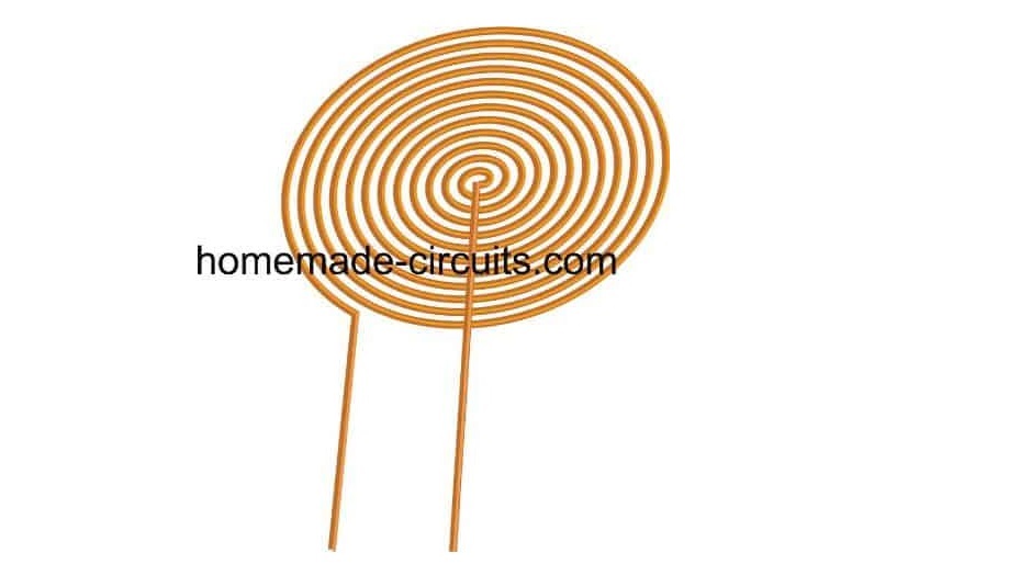
The bifilar coil type design shown above can be effectively implemented for making your homemade induction cookware.
For optimum response and low heat generation within the coil make sure the wire of the bifilar coil is made using many thin strands of copper instead of a single solid wire.
Thus, this becomes the work coil of the cookware, now the ends of this coil simply needs to be integrated with a matching capacitor and a compatible frequency driver network, as shown in the following figure:
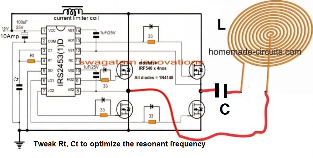
Parts List
- 33 Ohms 1/4 watt 5% = 4 nos
- Rt = To be determined by experimentation.
- 1uF/25V Electrolytic = 2 nos
- 100uF/25V Electrolytic = 1 no
- Ct and C = To be determined by experimentation.
- 1N4148 diodes = 4 nos
- MOSFETs IRF540 = 4 nos
- IC IRS2453 = 1 no
- Work Coil = As shown in the diagram. Diameter will need to be experimented.
- Current limiting Inductor = Can be between 1 mH to 5 mH. Again this one will need to be experimented.
- While experimenting the unknown components make sure to use a 12 V, 50 watt watt bulb in series with the DC supply line, to avoid accidental damage to the MOSFETs.
Designing the H-Bridge Series Resonant Driver Circuit
So far the information should have enlightened you regarding how to configure a simple induction cookware or an induction cooktop design, however the most critical part of the design is how to resonate the coil capacitor network (the tank circuit) into the most optimal range so that the circuit works at the most efficient level.
Enabling the coil/capacitor tank circuit (LC circuit) to operate at their resonance level requires the inductance of the coil and the capacitance of the capacitor to be matched perfectly.
This can happen only when the reactance of both the counterparts are identical, that is the reactance of the coil (inductor) as well as the capacitor are approximately the same.
Once this is fixed you can expect the tank circuit to operate at its natural frequency and the LC network reaching the resonance point. This is called a perfectly tuned LC circuit.
This concludes the basic induction heater circuit designing procedures
You may be wondering regarding what is resonance of an LC circuit.?? And how this may be calculated quickly for completing a specific induction heater design? We will comprehensively discuss this in the following sections.
The above paragraphs explained the fundamental secrets behind developing a low cost yet effective induction cooktop at home, in the following descriptions we will see how this can be implemented by specifically calculating its crucial parameters such the resonance of its tuned LC circuit and the correct dimension of the coil wire for ensuring an optimal current handling capacity.
What is Resonance in Induction Heater LC Circuit
When the capacitor within a tuned LC circuit is momentarily charged, the capacitor tries to discharge and dump the accumulated charge over the coil, the coil accepts the charge and stores the charge in the form of magnetic field. But as soon as the capacitor has discharged in the process, the coil develops an almost equivalent amount of charge in the form of magnetic field and it now tries to force this back inside the capacitor, although with an opposite polarity.
Image courtesy:
The capacitor is again forced to charge but this time in the opposite direction, and as soon as it's fully charged, it yet again tries to empty itself across the coil, and this results in a back and forth sharing of charge in the form of an oscillating current across the LC network.
The frequency of this oscillating current becomes the resonance frequency of the tuned LC circuit.
However due to inherent losses the above oscillations eventually die out in the course of time, and the frequency, the charge all come to an end after sometime.
But if the frequency is allowed to sustain through an external frequency input, tuned at the same resonance level, then that could ensure a permanent resonance effect being induced across the LC circuit.
At resonance frequency we can expect the amplitude of the voltage oscillating across the LC circuit to be at the maximum level, resulting in the most efficient induction.
Therefore we can imply that, to implement a perfect resonance within an LC network for an induction heater design we need to ensure the following crucial parameters:
1) A tuned LC circuit
2) And a matching frequency to sustain the LC circuit resonance.
This can be calculated using the following simple formula:
F = 1 ÷ 2π x √LC
where L is in Henry and C is in Farad
If you don't want to go through the hassles of calculating the resonance of the coil LC tank through formula, a much simpler option could be to use the following software:
LC Resonant Frequency Calculator
Or you may also build this Grid dip meter for identifying and setting the resonance frequency.
Once the resonance frequency is identified, it's time to set the full-bridge IC with this resonance frequency by suitably selecting the Rt, and Ct timing components. This may be done by some trial and error through practical measurements, or through the following formula:
The following formula can be used for calculating the values of Rt/Ct:
f = 1/1.453 x Rt x Ct where Rt is in Ohms and Ct in Farads.
Using Series Resonance
The induction heater concept discussed in this post uses a series resonant circuit.
When a series resonant LC circuit is employed, we have inductor an (L) and a capacitor (C) connected in series, as shown in the following diagram.
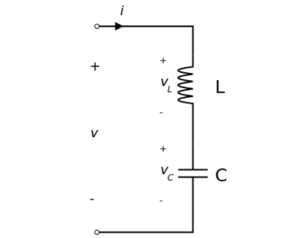
The total voltage V applied across the series LC will be the sum of the voltage across the inductor L and the voltage across the capacitor C. The current flowing through the system will be equal to the current that's flowing through the L and the C components.
V = VL + VC
I = IL = IC
The frequency of the applied voltage affects the reactances of the inductor and the capacitor. As frequency is increased from a minimum value to a higher value, the inductive reactance XL of the inductor will proportionately increase, but XC which is the capacitive reactance will decrease.
However, while the frequency is being increased there will be a particular instance or threshold when the magnitudes of the inductive reactance and the capacitive reactance will be just equal. This instance will be the resonant point of the series LC, and the frequency can be set as the resonant frequency.
Therefore, in a series resonant circuit, the resonance will occur when
XL = XC
or, ωL = 1 / ωC
where ω = angular frequency.
Evaluating the value of ω gives us:
ω = ωo = 1 / √ LC, which is defined as the resonant angular frequency.
Substituting this in the previous equation and also converting the angular frequency (in radians per second) into frequency (Hz), we finally get:
fo = ωo / 2π = 1 / 2π√ LC
fo = 1 / 2π√ LC
Calculating Wire Size for Induction Heater Work Coil
Once you have calculated the optimized values of L and C for the tank circuit of the induction heater and evaluated the exact compatible frequency for the driver circuit, it's time to calculate and fix the current handling capacity of the work coil and the capacitor.
Since the current involved within an induction heater design could be substantially large, this parameter cannot be ignored and must be correctly assigned to the LC circuit.
Using formulas for calculating wire sizes for an Induction wire size may be a little difficult especially for the newcomers, and that's exactly why a special software for the same has been enabled in this site, which any interested hobbyist can use to dimension the right size wire for your induction cooktop circuit.


Comments
Hi Swagatam,
I am trying to make an induction heater using the attached circuit, I did a bit of research and found this circuit to be best suited. I also got this board fabricated. But, unfortunately, can not get the board working. Can you help me in this? I can also provide the designed PCB and the BOM
Hi Muhammad,
You should always test the prototype on perf-board first before designing the PCB, because a rough testing is always required before finalizing the PCB design.
Looking at your schematic, I cannot figure out how will the circuit oscillate? It seems it is a ZVS circuit.
Can you compare the following design with your design and modify your design accordingly, because the following circuit is a tested design:
https://www.homemade-circuits.com/wp-content/uploads/2019/08/induction.png
https://www.homemade-circuits.com/simple-induction-heater-circuit-hot/
Yes, that’s the exact issue I am facing, it’s not resonating. According to the online sources, the earlier design I attached works, even so that the Gerbers are also available. But as you mentioned it does not resonate.
However, I made a comparison of both the circuits and found no difference in the logic rather than some resistors and diodes from the MOSFET gates to prevent latch-up and Vg going greater than manufacturers recommendation.
What now
I would suggest to start again afresh and try on a strip board first and test the rough sample thoroughly and then prepare the PCB.
Please refer to the following post and try the basic design which suits your requirement:
https://www.homemade-circuits.com/simple-induction-heater-circuit-hot/
If you have any issues, please let me know.
I am trying to design a small temperature controlled (likely PID) induction circuit and solenoidal coil for heating a thin walled tube of ferritic or martensitic stainless steel. I am a mechanical engineer with limited electrical engineering knowledge. I am trying to learn as much as I can about this. Eventually id like it to go into a consumer product driven off battery power. I will be going through your site more in the the near future. Thank you so much for all of the documentation and for your time and any advice you may provide.
Thanks Brian, I appreciate your interesting feedback.
You can also refer to the the following post for more relevant information.
https://www.homemade-circuits.com/simple-induction-heater-circuit-hot/
Let me know if you have any further doubts or questions…..
Just saw 50,000 questions WOW you have answered, you are the man. Anyway finished my sg3525 project,is there away to send you a picture of my Frankenstein. I? t worked right away, can’t say that for the ZVS driver. Few things to work out the mosfets get very hot quickly they never blew up. I an thing maybe a inductor to limit the current. Also I am only using 3 turns center tap and 3 more turns, I did have 5 got more output with ,3. Also just did a half bridge, just couldn’t see blowing up 4 more mosfets. I bought 10 only have to left. Thanks all of your circuts and the detailed instructions help me out a lot.
Great! That sounds awesome! You can send the results to my email ID
homemadecircuits
@gmail.com
I will check them out.
Will do when i am done, working on it now and waiting on so more parts.
OK…good!
I found this on your site, looks like this may work. I found another guy circuit, I didn’t see a place to send attachment, but at the end of his blog he said it didn’t work. From your print I can use a FET driver, it may need a few more parts I am going to give it a try.
Thanks you for the web site you have, if I look hard enough I can find everything I need. You are are a God of sorts in electronics.
Thanks so much art, for your kind feedback, glad you found this site useful,
let me how it goes…and if you have any further questions…
sir
I wanted to get in touch with you to discuss an induction heating mechanism for a professional pizza oven. I want to send you some 3D images (3D PDF) files and then explain my concept to you and subsequently discuss the design. Can you share your email id and your consent for the same? i would love to have your feedback and comments before proceeding with a prototype.
Hello SUBRAHMANYAM, Thank you for contacting me.
I really wish I could help you with your project, however unfortunately my knowledge about induction heaters is limited to small units only, and it can be difficult for me to provide my help on large professional designs.
If you have any basic questions regarding the concept, I can definitely try to solve it for you.
Hi Swagatam;
I have a hair dryer core heating resistor as known there are double resistors spring / coils and a thermal fuse. Multimeter shows the resistor value as about 35 Ohm.
And also 0.22 uF capacitor is connected between mains. And shunt resistor on the capacitor is 1M Ohm.
I assume that it is about 1500 Watts. I would like to convert it to hot air soldering gun but removing the thermal fuse and adding a strong enough dimmer circuit at first.
So I need your support / opinion accordingly.
Best Wishes.
Hi Suat,
Yes you can connect the load with a light dimmer circuit rated to handle 20 amps or above.
You can refer to the following post for the circuit designs:
220V Light Dimmer and Ceiling fan Regulator Circuit [Using Triac and Diac]
I am grateful for the support however to your opinion it is possible to say that hair dryer resistor absolutely would be efficient to some extent of melting the solder?
Best Wishes
You are welcome Suat, yes ,
if the hair dryer temperature is able to reach above 200 degrees Celsius, and if the hot breeze is held very close to the solder then definitely it will be enough to melt the solder
Hi
Apologies for a potentially dumb question that’s more ‘weird idea confirmation’ than technical. I hope it’s ok and that you can help. I’ve a potential use case for induction heating. I’ll have a long, thin piece to be heated (a cylinder approx 120-150mm by 3mm). The induction coil will necessarily be somewhat elliptical and orientated such that its coil is in line with the piece to be heated (long axes aligned) and separated by approx 30-50mm.
If (by some miracle) I’ve made this all clear enough to understand, is it even realistically possible to controllably heat the piece? Will the distance and orientation of the piece to coil make it impractical?
Thank you so much for any input you can give. I very much appreciate your taking the time to help out.
Hi, the material to be heated will need to be placed inside the induction coil, and not outside. If you place it outside the coil then it won’t heat up optimally. Otherwise there are no issues for heating the element. To have a controlled heating you will need to control the current input to the induction heater from an external source.
Thank you for that. Yes, the material to be heated will be inside the coil, just separated from it by around 40mm. I just wanted to get a feel for the feasibility of heating a long(ish), thin piece from that distance without some industrial-scale hardware. ???? Didn’t want to embark on a project that was doomed to failure. Thanks again.
No problem, the intended longish metal can be heated using conventional induction heater circuits.
Thank you again. ????
Hello ! I would like to recreate this heater for my end-of-semester project. May I know all the materials that were used for the circuit?
Hi, I have added the parts list under the circuit diagram. However, please note that the above design has not been verified by me practically, so please proceed only if you have understood the concept perfectly and are confident about its working.
Hello
my induction cooker at home is 1200watts. I want to modify the same for 200watts.
How to do?
Hi,
You simply have to reduce the input current from the power supply so that only 200 watts can reach the induction heater.
Hello
to reduce current I have to reduce the DC voltage . Now it is 330V DC. What will be the best method with minimum loss to reduce it to say 100V DC ? By using mosfet switching ; I see loss of power which is not acceptable. If it can be done without power loss ?
thanks
Yes a PWM switching can help to reduce the output current to the desired lower limits. You can use a 555 IC and mosfet based PWM switching.
The circuit from the following article can be tried. You will have to replace the mosfet with a 500V mosfet, and supply the 555 circuit with a separate 12V Dc. The lamp can be replaced with the induction heater.
https://www.homemade-circuits.com/dc-lamp-dimmer-circuit-using-ic-555/
It was very nice and How can i make it my self
Thank you, the easiest way to make is to buy a ready made unit and learn the concept and then replicate the parts.
Thank you so much.
So, how to find a solution in this circuit to solve this problem.(in case of very high voltage on resonant coil and capacitor). Is the purpose of the diodes and current limiter coil in this circuit to prevent this?
Also my second question, how can we decide whether the inductance of the current-limiting coil in your circuit, Should it be equal to the coil in the load or how many Henrys this coil should be?
Thanks in advance.
I have only presented an experimental design. The exact values of the coils and the capacitors are unknown and will need to be found through experimentation.
For current limiting you an modify the Ct of the IC through a BC547 transistor as shown in the following diagram:
https://www.homemade-circuits.com/wp-content/uploads/2021/12/h-bridge-induction-heater.jpg
Hello , I have three question. Please could you answer these?
How many mh is the coil you used in this load?
And the impedance increasing with high frequency that you apply on the coil and capacitor , does not damage the mosfets and the driver? How did you prevent this?
And if we connect the pwm generator from the outside, what kind of change should we make in the circuit?
The coil mH is not known, you will have to experiment it with some trial and error. You can use a 200 watt bulb in series while testing which will ensure that as long as the resonance point is not found the bulb absorbs all the current and prevents the mosfets from burning. As soon as the resonance point is hit the lamp illumination must decrease and fade out, indicating that the resonance has been achieved. Adding pwm will be a complex thing but you can do that by chopping the low side mosfet gates.
The damage to the mosfets can be also prevented by using a current controlled input power supply, whose current must be lower than the mosfet’s maximum handling capacity.
Thank you for your answers.
For example, 5 kw(2500 (wl) empedance and 2A) load occurs on the resonant coil and resonant capacitor , does this affect the other side of the circuit(mosfet side ) ?Because in resonance total empedance is very low , so we can drive 2a to coil with low power (maybe with 250W).
As the load increases the resonance effect will tend to get weaker due to lack of current and then the mosfets will have to pump the resonance effect by supplying more current to the LC circuit, in this way the mosfets will be affected and will need to maintain the required amount of current to the LC circuit to sustain the resonance effect.
Hello again, Can the coil and the transistor series resonate with the pwm produced by driver?
Shouldn’t there be ac voltage in the circuit for resonance? Or , Can this resonance be achieved with PWM and DC supply?
Hi, there’s no PWM here, only rectangle wave frequency from the IC which can be adjusted by adjusting Rt, Ct values. The output across the coil and capacitor will be AC since the mosfets are arranged in a full bridge network
Sir I will be highly obliged if you can kindly send me the electronic diagram of induction heater . Thanks in advance
Kayomarz, you can find the diagram in the following link:
https://www.homemade-circuits.com/simple-induction-heater-circuit-hot/
Thankyou Mr Swagatam
You are welcome Kayomarz.
what would be best way to build 500 watt induction coil in 120mmby 80 mm size pancake form? Should we use two coils or 24 coils in 20mm dia all in series to get uniform heating ?
Designing induction heater coil will require a lot of calculations, or it can be done by checking a ready-made induction heater….judging the coil specs manually may not be possible.
Thanks for the quick reply Swagatam.
DN
Hello David, I do not have a PCB designer with me at the moment, if I find one will surely let you know…
Swagatam,
Looking for a PCB designer and manufacturer who can produce a simple coil circuit for Interra Sciences.
Please email me at
Can send photo of the prototype circuit if you send your email.
Thanks,
David Newman
Thank you Zahid, I appreciate your interest and truly wish I could provide my consultations, however due to work pressure and lack of time it may not be possible for me at this moment of time.
Hi swagatam
I got your blogging site impressive..your descriptive content abt induction heating is helpful.we are an induction based company in pune
We need your practical consultation in our company.I also mailed u.plz revert back.